
Two signal system outages at Wellington Station in March and May 2025 stopped trains and disrupted commuter services. The same battery charger and power supply module failed on both occasions. TAIC found the installed power supply capacity was undersized, KiwiRail’s design and project management standards were not fully applied, and the alarm system did not draw attention to the fault.
Executive summary Tuhinga whakarāpopoto
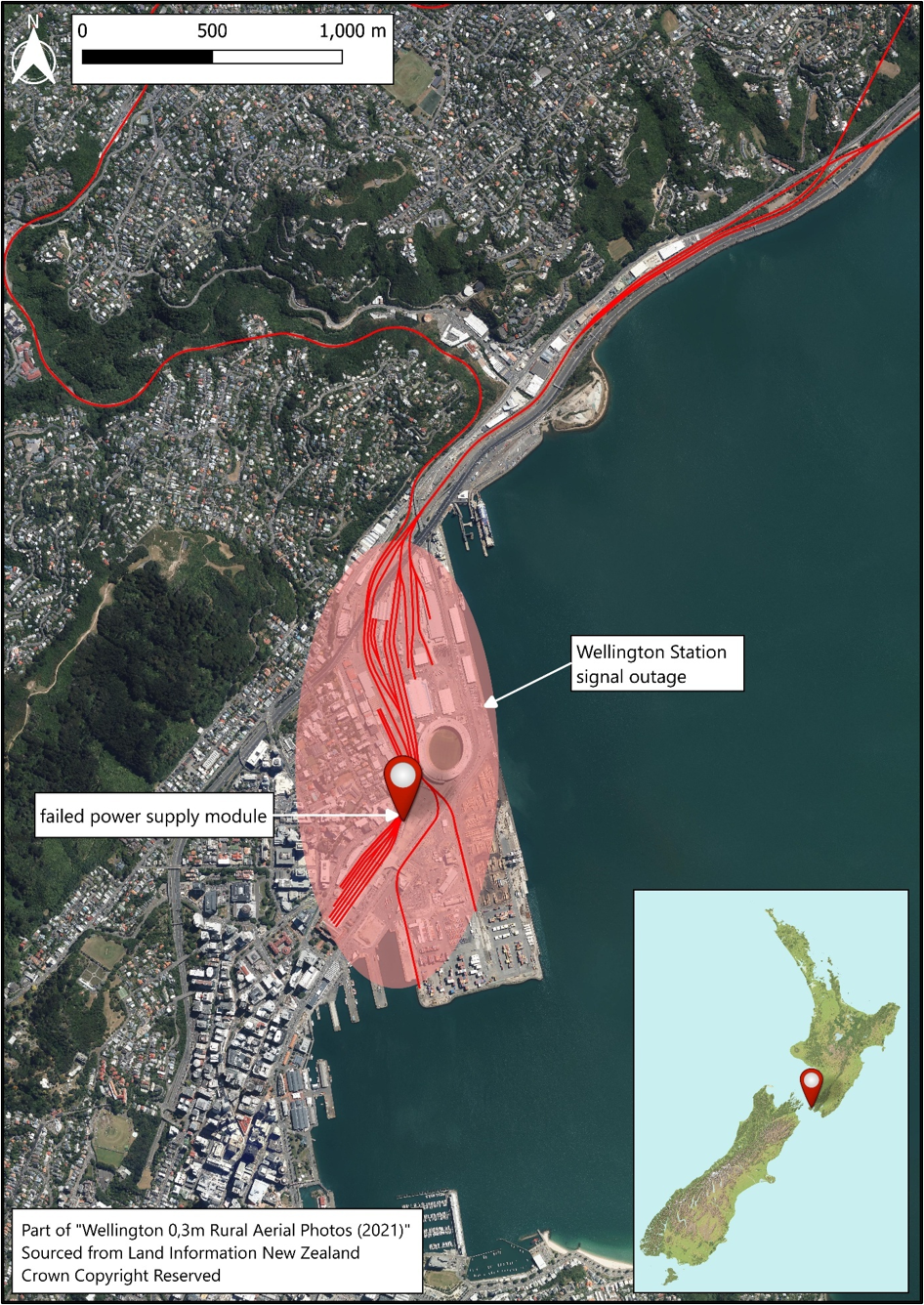
What happened
- In March and May 2025, Wellington Station’s signalling system, which had been replaced a few months earlier, suffered two significant outages caused by the failure of the same power supply module.
- Each failure resulted in all signals within the station reverting to ‘stop’ and disrupting commuter services. The failures required operational workarounds to disembark passengers and equipment replacements. Both failures were caused when the power supply module stopped charging its associated backup battery bank.
Why it happened
- Both outages were the result of weaknesses in the design, installation and operational oversight of a critical power supply system. In the first outage the failure in the power supply module was not addressed. This is because the design of the train control system’s on-screen alarm was ineffective, and therefore it did not attract the operator’s attention and alert them to the fact that there was an outage. This led to a backup battery discharging and the signalling computer shutting down.
- Prior to the second outage, a replacement power supply module had been installed but it was unintentionally configured into a mode (calibration mode) that limited its output capacity and inhibited its alarms. The backup battery discharged until the signalling computer shut down. This time the power supply module alarm output signal did not activate, which prevented the train control system from displaying an alarm to advise the operator.
- KiwiRail project documentation and management standards had not been fully applied, which meant KiwiRail did not identify that the power supply module’s spare capacity was less than what was required. Additionally, the operators had not been trained to respond to the power supply alarms when they were displayed on the train control system screen.
What we can learn
- These incidents underscore the need for robust change management and independent technical review during major infrastructure upgrades involving safety-critical systems.
- Alarm and information displays should be designed with human factors in mind to ensure that operators identify, understand and act upon safety-critical information. Operator training should align with new procedures and systems.
Who may benefit
- Rail system owners and infrastructure managers, train control room operators and their trainers, engineers and designers of alarm and monitoring systems for high-reliability infrastructure may benefit from the findings and recommendations in this report.
Factual information Pārongo pono
Background
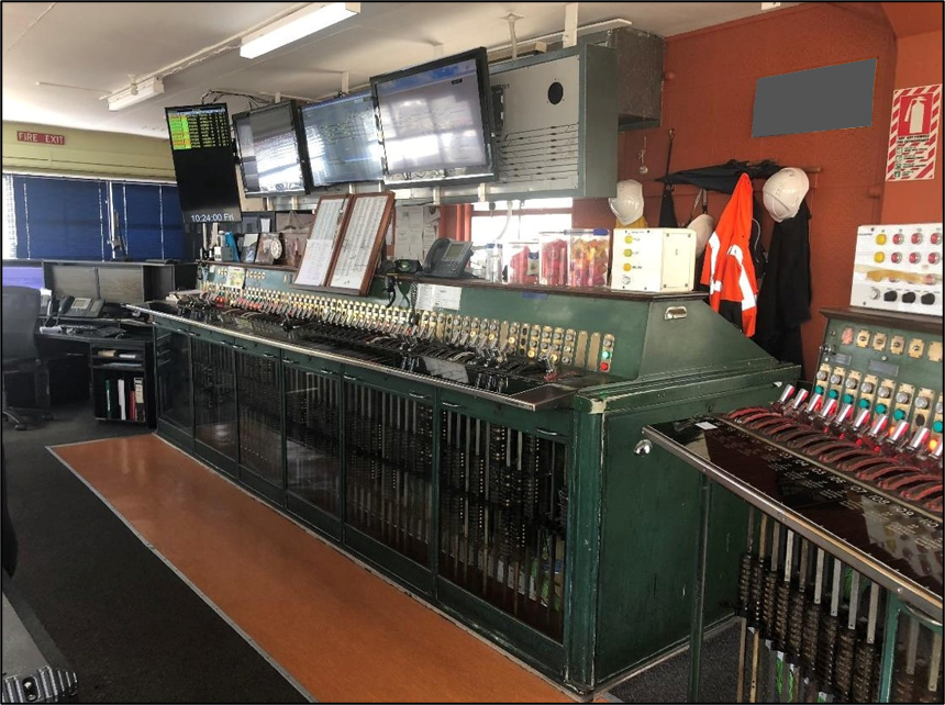
- The Wellington station area had been controlled from ‘A-Box’ (the name given to the staffed signal box next to the tracks in the Wellington Station approaches) with a manual signalling system since its construction in 1937. This system consisted of a 127-lever Westinghouse Brake and Signal Company power lever frame (see Figure 2).
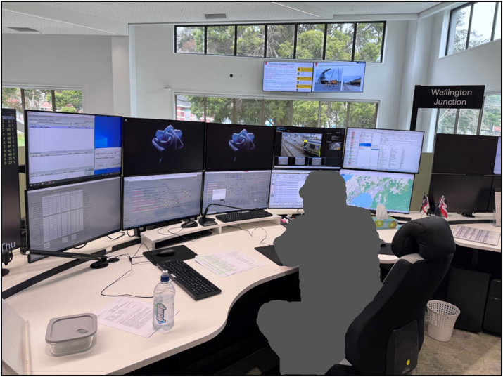
- This system was replaced over the 2024/25 Christmas holidays as part of the Wellington Station resignalling project. The replacement consisted of upgrading the signalling infrastructure and relocating the signallers from A-Box to the Wellington Regional Operations Centre (WROC). The Wellington Junction train control desk at WROC is shown in Figure 3.
- The resignalling was a complex project and involved 52 new railway signals, four equipment huts, 6 kilometres (km) of cabling route ducting, 2 km of new track, 14 new turnouts (a section of track allowing trains to switch from one track to another) and 23 new overhead line structures throughout the wider station area (Phillipsen, Kilby, & Cox, 2025). The resignalling project was led by KiwiRail, with the signalling scope of the project delivered by Siemens Mobility Pty Ltd (Siemens).
- In 2025, on a standard weekday there were approximately 390 scheduled passenger train movements arriving and departing Wellington Station. Outside of the morning and evening travel peaks, excess trains were stored in the yards, which were near the station. During peak travel times there were approximately 45 trains per hour, and outside of the peak times there were approximately 22 trains per hour.
- The movements of all trains in and out of Wellington Station, whether to the suburban stations of the Wellington commuter network or into adjacent yards, was controlled by the signaller at WROC.
- Detailed knowledge of the track layout at Wellington Station is necessary to facilitate these movements. This knowledge is supported by a mimic screen, which shows the status of signalling and track equipment and the locations of trains within the Wellington station area (see Figure 4).
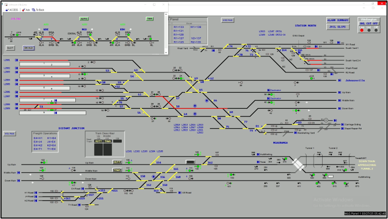
- The mimic screen was used by the signaller to set routes for trains to follow, and it displayed other critical information such as alarms about the network status.
- The mimic display was created with a software application called RealFlex and displayed on a large computer screen. It provided the operator’s user interface to KiwiRail’s train control system.
- During times when there were fewer passenger service trains running in the station area, the Wellington Junction desk was not occupied by a signaller. Instead, the Wellington regional train controller monitored the area.
- The train control system in the Wellington area was a computer-based interlocking system that used Westrace controllers (the Westrace controller is a modular, computer-based interlocking control system that was installed to manage and control train movements on the railway in Wellington Station. It can be thought of as a computer that uses logic to control switches and signals to ensure trains can move safely and avoid collisions) manufactured by Siemens.
- The computer-based interlocking system consisted of multiple Westrace controllers distributed around the rail network. These controllers were connected to the rail track and signals and operated remotely through a RealFlex user interface centred on the mimic screen.
- KiwiRail was in the process of upgrading its train control system at the time of the incident. This upgrade would replace the RealFlex user interface with a new rail traffic management system called ICONIS, set to be used in the Wellington station area from October 2025.
Narrative
First occurrence
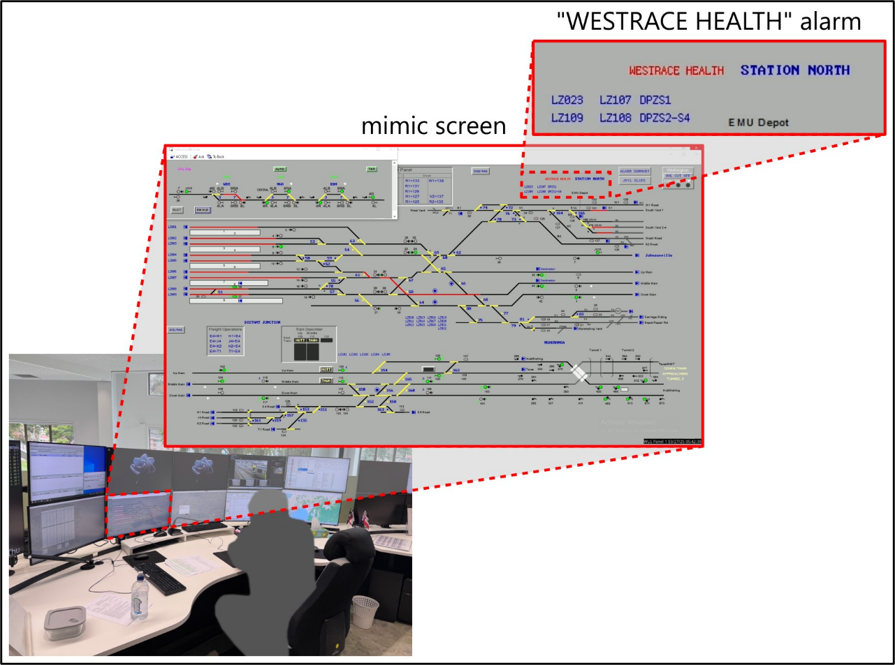
- From before 0200 (times used in this report are New Zealand Daylight Time (Universal Time Coordinated + 13 hours) and are expressed in 24-hour mode) on 27 March 2025, a visual alarm was regularly displayed at the WROC workstation for the Wellington regional and junction desks that stated ‘WESTRACE HEALTH’ (see Figure 5). That alarm was displayed on train control’s mimic screen for about five seconds, every eight minutes until the power outage occurred.
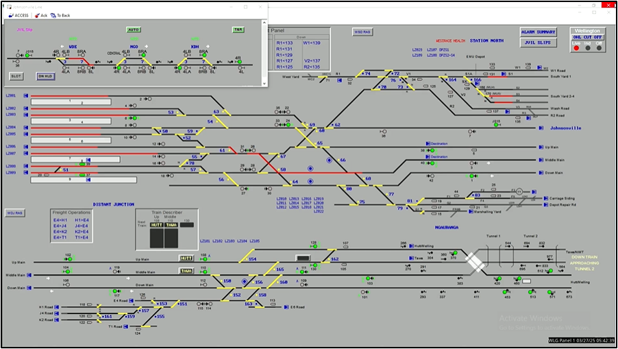
- The WESTRACE HEALTH alarm indicated that there was a power supply problem within the computer-based interlocking system in the Wellington station area. The operators were not aware that this alarm existed prior to the event.
- At 0430 on 27 March 2025 the rostered signaller began their shift at WROC. Prior to the signaller beginning their shift, the Wellington station area was controlled by the Wellington regional desk.
- Between 0536 and 0550 the signaller set routes for four trains to depart the station. During this period the visual power supply alarm was displayed twice and not seen by the signaller.
- At 0558, the signaller set the route for the first passenger train arrival of the day at the station.
- At 0559, the signaller lost the ability to set routes through most of the Wellington station area due to the interlocking system losing power. All the signals in the area reverted to red to stop all train movements.
- Without the ability to move trains into the station platforms, the next scheduled arrivals were held at suburban stations. Passengers were disembarked to find alternative transport. The only train that was within the station limits was moved through the area under the signaller’s verbal authority to allow its passengers to disembark on one of the platforms at Wellington Station.
- Signalling technicians were called out to identify and resolve the fault. They found that a power supply module in equipment hut M0005, Rack A, had failed. They replaced the power supply module and the train control system gradually returned to normal. Train services were back running to usual schedules by about 0830.
Second occurrence
- On 14 May 2025 at 1730, train control experienced further intermittent signal failures at Wellington Station. Trains were moved slowly and safely within KiwiRail’s rules and procedures, until 1812, when the signalling system in Wellington failed.
- Prior to the failure, no alarms were visually or audibly presented on the train control mimic screen to indicate that there was a problem with the power supply system.
- The signals maintainer was called out to identify and resolve the fault. They found that the power supply module they had replaced in equipment hut M0005, Rack A, on 27 March 2025 had failed. It was replaced, and trains were operating normally by 1845.
- On the second occasion, the failure was later identified to have been due to the power supply module being unintentionally switched to calibration mode. This was a factory test setting, not intended for field use, that limited the output power of the power supply module to approximately 50 per cent of its selected capacity (the output power could be selected in steps from 500 watt to 1000 watt). Calibration mode also inhibited the failure alarm signals from the power supply module.
- This reduction in the power supply module’s output capacity meant that it could not support the standing load and maintain the charge current to the battery bank. If the power supply module was unable to supply the load current, it would protect itself by reducing output voltage then shutting down. The backup batteries slowly discharged. Without the batteries providing supplementary power to the system, the Westrace controller had insufficient power to operate and, as a result, it shut down.
Power supply module
- Four Westrace controllers were installed in equipment huts around the Wellington station area. The equipment huts were powered from a generator-backed ring main (a ring main is a closed loop wiring circuit which supplies power to multiple outlets from both directions). Inside each hut, the AC supply was converted to DC by a power supply module (Helios 110VAC/55VDC power supply type AMP-K3024). This power supply module float charged (a float charge is a type of low voltage charging that supplies a continuous low voltage to a battery to maintain its fully charged state) a battery bank and provided standing load (standing load refers to a constant, sustained power draw in an electrical system) to other elements of the railway system (see Figure 6).
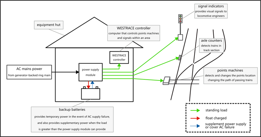
- If the AC supply failed, the generator would take over. The batteries ensured that the signalling system continued to operate uninterrupted until the generator connected to the ring main.
- The power supply module that failed was a standard product provided to Siemens by their supplier and used in the signalling system at Wellington Station.
- The battery was expected to provide power during periods of high load demand that were greater than the power supply capacity. The battery would then recharge when the rail traffic reduced between peak travel times. This design was approved by KiwiRail as part of the Wellington Station resignalling project.
Personnel information
- The Wellington signaller who was on duty during the first signalling system power outage had over 30 years’ experience working in A-Box. They had received training for the transition to working at WROC and were competent for the role.
Previous occurrence
RO-2017-102 Signalling irregularity, Wellington Railway Station, 3 April 2017
- A previous incident where the Commission made recommendations around change and design management was the investigation into signalling irregularities at Wellington Station in 2017.
- During the morning peak period on 3 April 2017, a route was set for a train movement that was not physically possible due to the design configuration of the track alignment. However, the route was available to the signallers according to their mimic screen.
- Due to this discrepancy, the train was directed into a section of track where there was the potential for a collision with an oncoming train. The driver realised that their train was routed down the incorrect track and stopped, but not before the train had entered a potential collision zone. There was no collision and no one was injured.
- Following an investigation into the incident, the Commission recommended that KiwiRail review its change management processes for modifying and building new safety-critical systems, and ensure that these processes include a full failure mode effects analysis and functional testing before the new or modified systems are put into service.
- In response to the recommendation, KiwiRail improved its processes for scoping, design and testing of significant changes to safety-significant control systems. This included:
- identification of potential failure modes in the scoping phase
- formal documentation of issues discovered throughout the testing process
- formal technical and user sign-off before implementation
- post-implementation review and associated issues tracking to capture and resolve residual issues.
Organisational information
- KiwiRail Holdings Limited (KiwiRail) is a New Zealand state-owned enterprise. It controls rail movements on the national rail network and maintains the railway infrastructure as the rail access provider.
- Siemens Mobility Pty Ltd (Siemens) is an engineering solutions provider, specialising in the design, supply and maintenance of rail transport systems. Siemens was contracted by KiwiRail to design and deliver the signalling scope of the Wellington Station resignalling project.
Analysis Tātaritanga
Introduction
- On 27 March 2025, and again on 14 May 2025, the signalling system at Wellington Station experienced outages that caused significant delays to commuter transport. The outages on both occasions were caused by different failures of the same battery charger and power supply module within equipment hut M0005, Rack A. Both failures were caused when the power supply module stopped charging its associated backup battery bank.
- The power supply system included an alarm to alert train controllers and signallers to problems within the network. However, they were not aware of the existence of the power supply alarms. The ineffective alarm presentation meant that when the alarm activated, it did not draw the intended recipient’s attention to the failure of the power supply unit.
- The effect of the signalling system power outage on the rail network at Wellington Station was handled in a safe manner, due to the signals in the area reverting to red to stop all trains. However, the reliability of a signalling system is fundamental to its safe operation. Two power outages within the space of six weeks indicates a reliability problem within the signalling system. Reliability helps to eliminate safety risks from the operation of the signalling system before they have an opportunity to occur.
- The Commission’s investigation identified two safety issues:
- KiwiRail’s application of design and project management standards
- the need to consider human factors in alarm presentation.
- The following section analyses the circumstances surrounding the events to identify those factors that increased the likelihood of the events occurring or increased the severity of their outcome. It also examines any safety issues that have the potential to adversely affect future operations.
Why did the power supply module fail?
- The power supply module was designed to float charge the battery bank while also providing power to the standing load from other items in the signalling system. Siemens design criteria for the size of the power supply was that its capacity must be greater than 10 per cent above the maximum estimated load to ensure it could operate as intended. KiwiRail advised that the battery bank was intended to supplement the power supply output with peak load current and provide all power during mains outages.
- KiwiRail advised that the first occurrence when the power supply module failed was due to an internal component fault. It is not unusual for electronic systems to fail occasionally; therefore mitigation of the effect is usually part of the design. Typically, power supplies for critical equipment are monitored remotely and rated for more than the maximum load or duplicated to allow redundancy.
- A remote alarm was generated when the power supply module failed, and the alarm was shown on the mimic screen at train control. However, the remote alarm was not noticed, and as a result the fault was not investigated.
- After the power supply module failed, the battery bank kept the signals operational for several hours, but the battery voltage gradually dropped to a level where the Westrace controller was no longer able to operate. It shut down, resulting in the first signal outage.
- The power supply module was replaced and the system tested. However, the Wellington signalling system failed with similar operational outcomes about six weeks later. On this occasion, the failure was due to the power supply module being unintentionally switched to calibration mode. KiwiRail described that as a factory setting that neither they nor Siemens knew existed.
- The power supply module gave no indication that it had been switched to calibration mode. This mode was understood to have been selected by usual actions that a technician might carry out during normal installation of the power supply, made in a specific sequence. Siemens advised that a subsequent firmware upgrade to the power supply module will generate an alarm if it is switched to calibration mode during installation.
- On the second occasion, the remote power supply alarm system did not activate as intended and the signaller did not receive any warning of the issue with the signalling system power supply. This was due to the power supply being in calibration mode. A remote alarm from another source was transmitted approximately 20 seconds before the failure (there were several other alarms related to the power supply combined into a single remote alarm).
- The Commission’s review of the signalling system’s electrical drawings and power supply load calculations for Rack A in equipment hut M0005 revealed that the installed power supply capacity was undersized. The power supply module’s spare capacity was less than the design criteria set by Siemens (the spare capacity for Rack A in equipment hut M0005 was 1.6%).
- This shortfall posed an operational risk, as the configuration of the DC power supply in Rack A may not support full system functionality under peak load conditions or over a longer term. The limited capacity increased the vulnerability to potential disruptions through an inadequate battery-backed DC power supply to safety-critical systems.
Design assurance process for safety-critical systems
Safety issue 1: The design and assurance process for the auxiliary power supply system was inadequate to ensure the continued operational functionality of the safety-critical signalling system.
The Westrace controller that provided the computer-based interlocking system was critical for the safety of trains and passengers travelling on the network. Its operation had been tested and was proven to operate in a very safe manner during its construction and commissioning. It was also proven to fail to a safe condition (failing to a safe condition means that if any part of the system malfunctions it automatically defaults to the safest possible state, usually displaying a stop indication at all relevant signals). These two key factors were required to achieve its Safety Integrity Level 4 (safety Integrity Level 4 is the highest level in the international functional safety standard (IEC61508/CENELEC). It is used in critical systems where failures have catastrophic potential, such as railway signalling) rating.
- To ensure that the signalling computer was not affected by mains power disturbances, its power supply was backed up by a generator and a battery. The power supply status was also monitored remotely 24/7 by train control to ensure a quick response to a fault.
- The Commission found that the power supply system designed for this critical safety system had not adequately considered the reliability of DC power supply in equipment hut M0005, Rack A. The power supply module depended on the battery bank to supplement peak load current, but the battery backup was not treated as a critical subsystem for continued operation of the signalling system. The power supply module was configured as a float voltage battery charger and power supply with a fixed voltage output. The voltage was set to match the optimum float charge voltage per battery cell in the battery bank.
- A reliable power supply and battery charging system for a critical safety system should have ample spare capacity to cover both the standing load and the charging load for the battery bank. It may also have additional features such as:
- power supply module duplication to provide full power supply redundancy
- isolation of the charger function from the standing load
- charge current limiting or current control to ensure optimum battery bank recharge rate and sufficient capacity for the standing load
- undervoltage shutdown to protect the batteries discharging to a level that could permanently damage them
- a timed boost-charge system to recharge the battery quickly and stabilise the charge level across the battery’s internal cells and across individual batteries in the battery bank
- automatic battery discharge test function
- remote monitoring to draw attention to a fault, demanding an operator response to clear an alarm (this aspect is explored further in Safety issue 2).
- The arrangement of the contractual responsibilities for the design and supply of the interlocking system and its integration with the existing KiwiRail train control system was within KiwiRail’s scope of control. The resignalling project as a whole involved multiple contracts and contractors with overlapping scopes of work and complicated integration at the interface boundaries. The project work would also have required considerable planning to coordinate equipment delivery, installation, commissioning and training over the Christmas shutdown period.
- KiwiRail had standards in place for design and project management to ensure that engineering designs were fit for purpose and adequately reviewed. KiwiRail high-level design management principles were set out in G-PR-AL-9025 Design Management and were linked to all the associated KiwiRail standards.
- The design management principle, G-PR-AL-9025, included processes to ensure that:
- a phased approach is used to develop the design, with approval from KiwiRail at each phase
- there is documentation of the key phases, such as design reports, hazard identification studies, risk assessments and mitigations, peer reviews, testing and commissioning records
- record of the verification and validation of the design is completed using the Design Review Sign-off Sheet.
- KiwiRail provided limited evidence to the Commission that demonstrated the processes under the design management principle had been carried out in relation to the resignalling project, or that a peer review of the DC power supply design had been adequately completed.
- Siemens had conducted an internal review of the power supply design. This design review covered the entire power supply system, including both the AC and DC power loading within each equipment hut and racks.
- Siemens engaged a separate consultant to conduct a peer review of the AC power supply system. The reviewer provided a Declaration of Conformity for this part of the overall design, confirming that it met the appropriate parts of the New Zealand Electricity Regulations 2010. However, this peer review did not cover the DC power loading, which is where the undersized power supply module was located.
- The DC power supply design calculations were all contained in Siemens’ power supply design documentation and showed that the power supply module in Rack A in equipment hut M0005 did not meet the design criteria. The summary sheet with this document set showed that its latest version was the ‘as-built’ version, signed off in June 2025, three months after the first signalling outage.
- KiwiRail also engaged an external consultant to review the AC power supply system. However, KiwiRail did not conduct their own peer review of the DC power supply design. If they had, it would likely have identified issues with the power supply module’s capacity to both support the standing load and charge the battery bank. It may have also questioned the reliability of the design to support a critical safety system.
- It is very likely that KiwiRail’s design and project management standards were not appropriately applied for the Wellington Station resignalling project. The signalling system failed twice in a predictable and repetitive nature that was identifiable through a review of the power supply system as part of the application of KiwiRail’s design and project management standards.
Effectiveness of the alarm system
Safety issue 2: The alarm system to alert train control operators that a fault existed in the signalling system that could affect train operations, was ineffective.
- In safety-critical operating environments, equipment is monitored remotely to alert operators to any faults. Any such alarms would generally be presented in a way that drew attention to them and required action. An alarm could be temporarily suppressed but only stopped once the source event had been rectified.
- The signalling system at Wellington Station sent an alarm to indicate the internal fault, but that alarm was displayed in a way that did not draw attention to it. Recordings of the train control mimic screen show that the alarm had been repeating for more than four hours.
Considerations for effective alarm system design
- Within a control room environment, alarm systems indicate an unexpected abnormal state of the system by providing visual and/or auditory stimulation to bring people’s attention to the event and convey relevant information. Such alarms are usually intended to change the operator's psychological state to alert, so they are ready to respond appropriately (Liu, Hwang, Hsieh, Liang, & Chuang, 2016).
- To be effective, alarm systems should, at a minimum, provide relevant information in a timely manner to the people who need to be alerted. Furthermore, well-designed visual displays consider human perception, cognitive models, and principles of attention and memory, and assist the operator in managing multiple individual alarms (Wickens, Gordon, Liu, & Lee, 2004) (Liu, Hwang, Hsieh, Liang, & Chuang, 2016).
- This is especially important in a busy operational environment such as a train control centre, where signallers and train controllers must maintain their attention on a range of tasks, using multiple screens in dynamic situations.
The RealFlex alarm design
- In the lead-up to the first outage, when the power supply module failed and stopped charging the battery bank, an alarm was triggered. This alarm was presented on the mimic screen at the Wellington Station and Wellington region train controllers’ desks.
- The alarm consisted of the words WESTRACE HEALTH in red font (see Figure 7). This text was displayed for five seconds at a time before disappearing, then reappearing after eight minutes. The alarm did not include an auditory component, which was reserved for safety-critical alarms. This alarm was not considered safety-critical. The power supply failure did not pose an immediate risk to operations as the signals reverted to red to stop all trains.
- The Commission identified three issues with the alarm’s presentation.
- First, the alarm system only alerted those in the train control centre. Those with the ability and responsibility to address any power supply issue (for example the signal maintenance team) were not included in the alarm system. Even when the alarm was unacknowledged for several hours, the system was not configured to escalate the issue any further. As a result, signalling maintenance staff were wholly reliant on train control to notice the alarm and inform them of the issue.
- Second, although the alarm activated as intended, interviews confirmed that no one working in the train control centre saw it. The Commission identified several contributing factors.
- It was not visually conspicuous, particularly in the context of the complex mimic screen. The text was red, which contrasted with the other on-screen text (mostly blue or black). However the mimic screen also uses red lines to indicate live trains, reducing the visibility of the alarm text.
- It was only visible on-screen for five seconds at a time, interspersed with eight-minute periods where the text was not visible. This meant that the text was only visible for one per cent of the time that the alarm was activated.
- Generally, train controllers use the mimic screen to monitor trains and control signals, so their attention would have been on the lines rather than the top of the screen where the alarm was shown.
- Third, even if they had seen the alarm, neither the train controllers or signaller had any knowledge about the alarm system, and the words WESTRACE HEALTH did not hold any meaning for them. They had not received any training on procedures for responding to such an alarm. As a result, they did not understand the implications of the alarm. This shows that the alarm had not been subject to user testing, which may have highlighted the design issues outlined above.
- The signaller, the train controllers and signal maintenance staff were unaware of the power supply issue until the outage occurred. The Commission found that it is virtually certain that this occurred due to:
- the inadequate alarm presentation
- a lack of user training for the alarm system.