Fire in engine room on factory trawler (quickly extinguished). Diesel oil sprayed onto hot engine exhaust, under pressure when an accumulator in the fuel system unwound from its pipe connector and dislodged. Lessons and recommendations for Marine sector relate to maintenance of safety-critical and remote-operated systems; Command and control for fire response; and design of gaseous fire-extinguishing systems.
Executive summary Tuhinga whakarāpopoto
What happened
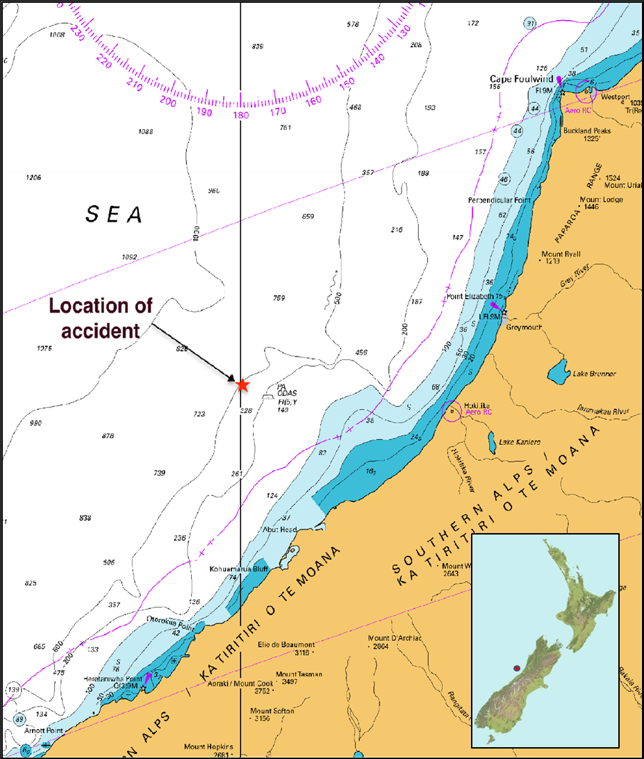
- On 2 July 2021, the factory fishing trawler Amaltal Enterprise was fishing off the west coast of the South Island, New Zealand. The main engine had been shut down to effect repairs to a low-pressure fuel pipe. About 50 minutes after restart, an accumulator installed in the main engine low-pressure fuel system unwound and dislodged from its pipe connector, allowing marine diesel oil at 8 bar pressure to jet upwards and ignite on the shrouded hot engine exhaust manifold.
- The crew closed down the engine room and the fire was quickly brought under control without the use of the fixed Halon (a liquified, compressed gas that stops the spread of fire by chemically disrupting combustion) gaseous fire-smothering system. The vessel suffered extensive heat and smoke damage to electrical systems and had to be towed to a safe port for repair.
Why it happened
- It is likely the accumulator dislodged due to any combination of the following factors.
- A lower-than-optimal torque being applied when fitting the connector into the accumulator during maintenance conducted approximately five weeks earlier by shore-based contractors.
- Vibration and resonance created by the machinery and propulsion system in the engine room.
- The ‘loose fit’ between the male thread on the connector and the female thread of the accumulator. Once the steel-on-steel connection between the two components was lost, lateral play between the two made the assembly more prone to vibration and afforded little resistance to the accumulator unwinding.
- The failure of the bladder within the accumulator meant the assembly was susceptible to pressure pulsing within the fuel system rather than achieving its purpose of absorbing these forces.
- There was no support bracket or any other means of preventing the accumulator from dislodging.
What we can learn
- It is important that repair and maintenance is performed under controlled conditions, such as following appropriate procedures for tagging out, checking, testing and signing off each task, particularly when working on safety-critical systems.
- Forced and resonant vibration in engine rooms can be problematic. It is important that components are secured against vibration to guard against the loosening, chafe or wearing, cracking and (in extreme cases) destruction of components, particularly safety-critical components.
- It is important that devices for disconnecting systems remotely are routinely tested to ensure that they function correctly during an emergency.
- When responding to an emergency, it is important that crew fully consider the important elements of command and control, specifically, accounting for all crew and establishing good communications.
- When a vessel has a fixed gaseous fire-extinguishing system, where the gas and associated release mechanisms are located in the space they are designed to protect, it is important that crew understand the longer they delay activation the higher the risk that fire will render these systems partially or fully inoperable.
Who may benefit
- Vessel crew, ship owners, ship operators, flag administrations and surveyors.
Factual information Pārongo pono
Narrative
- On 26 May 2021, the Amaltal Enterprise departed Dunedin with 44 crew members and one observer from the Ministry for Primary Industries on board and headed south to the sub-Antarctic Islands. Over the following 25 days the vessel fished in the area of the sub-Antarctic Islands before heading north up the west coast of the South Island to fish for species there.
- On 20 June 2021, the chief engineer was making rounds of the engine room when he noticed diesel oil leaking from a fractured pipe on the main engine low-pressure fuel system =. The engine was shut down and the leaking fuel pipe removed. A fitter repaired the fuel pipe, and it was reinstalled, after which the vessel resumed fishing operations.
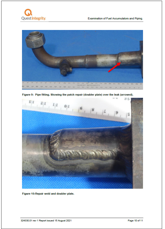
- After a further 12 days, at about 1345 on Friday 2 July 2021, the chief engineer noticed diesel oil leaking from the repaired pipe in the same fuel line. The Amaltal Enterprise was trawling for fish at that time about 55 nautical miles west of Hokitika, West Coast. The skipper hauled the nets and at about 1410 the chief engineer shut down the main engine. The leaking fuel pipe was removed and the same fitter effected a more permanent repair by welding a doubler (another steel plate is welded directly over the existing steel plate to encompass the crack) plate around the crack.
- By 1505, the engine crew had made the repair, refitted the fuel pipe, cleaned the affected area and pressurised the fuel system to check for leaks in the area. Finding no leaks, the chief engineer restarted the main engine at 1515.
- At 1516, the chief engineer engaged the main engine shaft generator and monitored the engine room for a period of time before leaving it for the workshop one deck above. The skipper began casting the nets to resume trawling. The weather was fine and clear with light winds and a slight sea running.
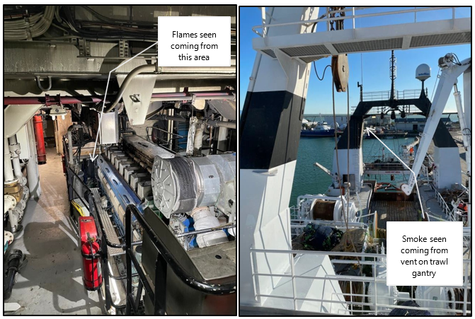
- At 1625, the engine room alarm sounded. The chief engineer left the workshop and, on descending the engine room stairs, saw flames near the forward left-hand side of the main engine (see figure 3). The chief engineer decided to not risk trying to reach the engine control room where the emergency stops were located, but instead retreated back up the stairs. At that time the main engine stopped and the vessel blacked out (lost electrical power to all systems due to the main shaft generator no longer being driven by the main engine). The chief engineer chanced on the deck watchkeeper at the top of the stairs and told them to go to the bridge and report the fire to the skipper.
- Meanwhile, on the bridge the skipper had noticed the main engine had stopped and, looking aft, saw thick black smoke coming from vents in the starboard gantry leg, which also doubled as the exhaust trunking for the main engine. The main fire alarm had not sounded, so at about the same time as the deck watchman arrived on the bridge to report the fire the skipper manually activated the general fire alarm.
- With the loss of the main engine the Amaltal Enterprise stopped and the trawl nets settled onto the seabed, effectively anchoring the vessel in the calm sea conditions.
Response to the fire
- The chief engineer closed the dampers (a normally-open flap that can be released to close and seal an opening) for the two engine room supply fans located on the port side of the trawl gantry. While the chief engineer was crossing the deck to close the exhaust vents on the starboard side, the emergency generator started up automatically.
- The chief engineer then tried to close the damper on the starboard No. 2 engine room exhaust fan, but it was running and thick smoke emanating from it made it impossible to close.
- The chief engineer then went to the bridge and asked the skipper to activate the three emergency stops on the bridge, which:
-
shut down systems associated with the main engine
-
stopped the accommodation ventilation fans
-
opened the breakers on the main switchboard that powered the main engine fuel pumps and other ancillary equipment.
-
- The chief engineer then returned to the main deck and succeeded in shutting the damper on the engine room exhaust fan, even though it was still running.
- The chief engineer then returned to the bridge and opened the door to the release cabinet for the engine room fixed Halon gaseous fire-smothering system. The purpose of doing this was to trigger an automatic stop connected to the cabinet door that would automatically stop the No. 2 exhaust fan. However, the fan continued running, so the chief engineer went to the emergency generator distribution panel and tripped the circuit breaker for the No. 2 exhaust fan, which caused the fan to stop.
- The chief engineer then went to the bosun store and activated the remote fuel shut-off valves, which isolated all fuel supply to the main engine.
- Meanwhile, in response to the general fire alarm, the crew had mustered at their fire stations and carried out the following tasks:
- started the emergency fire pump
- donned self-contained breathing apparatus (BA)
- ran fire hoses in preparation for boundary cooling.
- By about 1640 (times from this point are approximate based on crew members’ recollections), the crew observed that the smoke emitting from the engine room had decreased in volume and was lighter in colour. Believing that the fire had likely been smothered at that point, the skipper and chief engineer decided not to activate the fixed Halon gaseous fire-smothering system for the engine room and instead instructed the BA team of two to enter the engine room to conduct an inspection.
- Upon entry the BA team observed ‘a lot of smoke’ but could see no flames. They were able to relay this information to the other parties through the radio integrated into the BA facemasks. They then retreated and shortly after re-entered with a portable foam applicator and spread foam over much of the engine room. The BA team then retreated and the engine room was closed up again by about 1705.
- At 1735, the chief engineer together with the BA team re-entered the engine room. They observed a residual ‘haze’ but no fire. The chief engineer isolated a number of systems that had been damaged by fire and then they retreated, leaving the engine room closed for a further hour.
- At 1825, the chief engineer closed (connected them to the emergency switchboard) the breakers on the engine room fans and began ventilating the engine room. At about 1915, the skipper, chief engineer and second mate entered the engine room to assess the damage.
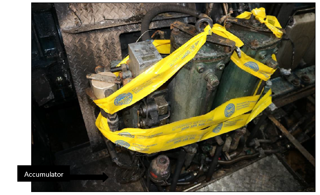
- At about 2000, the skipper and chief engineer re-entered the engine room to investigate the cause of the fire. They found that an accumulator (a pressure vessel installed in the low-pressure fuel system. Its purpose is to absorb shock-loading in the low-pressure fuel system caused by the high-pressure fuel pumps as they draw low-pressure fuel and deliver it to the injectors at high pressure) that should have been connected near the low-pressure fuel filter arrangement had separated from its fuel line and was lying on the tank top (the top boundary of tanks located at the very bottom of the engine room) below. They arranged for the open fuel line where the accumulator had been connected to be capped and then retreated to the bridge to plan next steps.
- Previously, the skipper had telephoned Talley’s technical manager and told them about the fire. In this subsequent discussion with management ashore they decided that it was not feasible to make the main engine operational, so it was decided that another company fishing vessel that was in the area would tow the Amaltal Enterprise to Nelson.
- By 1520 the following day, 3 July 2021, another company vessel had the Amaltal Enterprise in tow. Without the use of the main engine-driven shaft generator there was insufficient generator capacity to operate the trawl winches, so the trawl nets were severed and dropped to the seabed for later retrieval. At about 1500 on 5 July 2021, the tow had arrived off Nelson, where a Port of Nelson pilot boarded and (with the assistance of the harbour tugs) the Amaltal Enterprise was taken into the port.
Key personnel information
- The skipper joined Talley’s as a fishing deck hand in 1994 and has remained working for the company for 27 years. The skipper obtained fishing certificates and worked through the ranks on a number of Talley’s fishing vessels, being promoted to first mate in about 2006, then transferring to the Amaltal Enterprise in about 2009. The skipper obtained his Skipper Fishing Vessel Unlimited Certificate in March 2019 and was given their first command in 2020. The skipper was on the third trip as skipper at the time of the fire.
- At the time of the accident the chief engineer had worked for Talley’s for about 11 years (as a trainee engineer for about six months, as second engineer for about five-and-a-half years and chief engineer for the last four-and-a-half years). The chief engineer’s experience on the Amaltal Enterprise included nearly five years as second engineer and the four-and-a-half years as chief engineer. The chief engineer obtained a Marine Engineering Class 3 Certificate (MEC3) in October 2016, which was valid for ships with a main engine rating of up to 3000 kilowatts within New Zealand waters (within the New Zealand Exclusive Economic Zone (EEZ)).
- The second engineer had started with Talley’s as a trainee engineer in 2015. The second engineer obtained a Marine Engineer Certificate Class 5 (MEC5) in April 2018 and was soon after promoted to second engineer on another company vessel before transferring to the Amaltal Enterprise later that year.
- The second engineer had completed a Basic Firefighting Course and both the skipper and chief engineer had completed an Advanced Firefighting course.
- The skipper, chief engineer and second engineer all joined the Amaltal Enterprise at the start of the voyage in Dunedin on 25 May, about five weeks before the fire. All three held the appropriate qualification for their respective ranks on board for the accident trip.
Vessel information
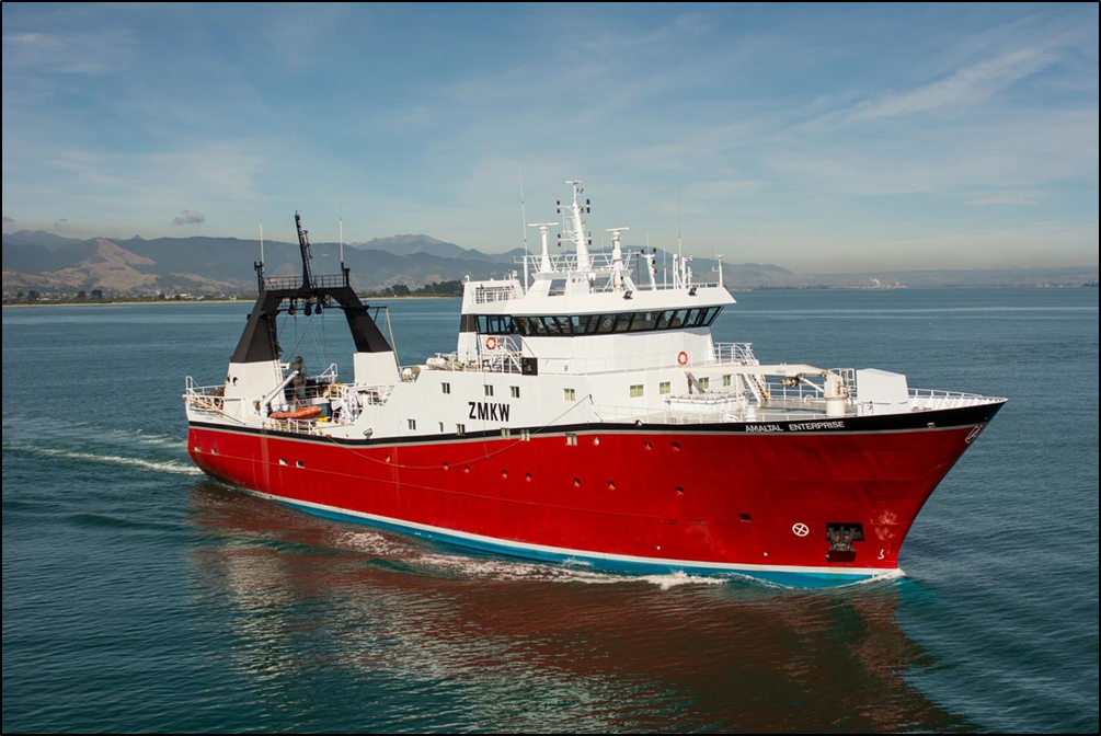
- The Amaltal Enterprise is a New Zealand-registered deep-sea factory fishing trawler. Species are caught, processed, packaged and frozen on board. It typically operates with a total crew of between 40 and 45, most of whom are employed working the various processing plants on board.
- The vessel was built in 1988 in Norway. It first entered the New Zealand ship registry in 2000 and was purchased by Talley’s in 2002.
- Main propulsion is provided by a single 3000 kilowatt Wartsila Vasa diesel engine, which also provides power for a shaft-driven main generator. A Cummins auxiliary engine provides power for an additional generator, with a second Mercedes generator providing emergency capacity via an emergency switchboard. All engines were being run on marine diesel oil.
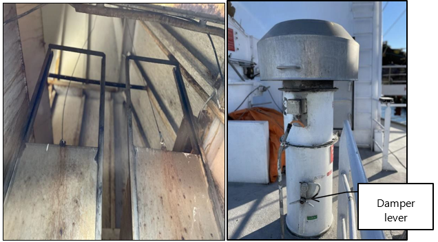
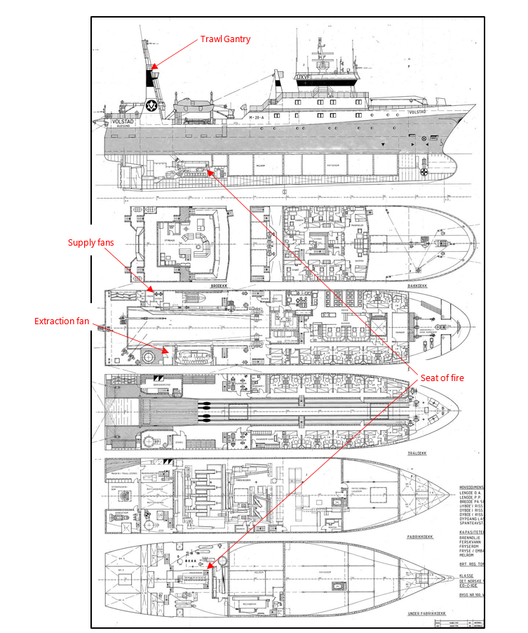
- Ventilation for the engine room is provided by two sets of electric-driven fans (Fan 1 and Fan 2) located on the port leg of the trawl gantry (see figure 3). Both fans supplied air into the port side of the engine room. Excess air was expelled from the starboard side via a natural vent located on the starboard trawl gantry leg and an extraction fan on the trawl deck that worked in tandem with supply Fan 2. Each vent was fitted with a sliding type quick-closing fire damper and fan with a butterfly type damper within the fan trunking (see figures 4 and 5).
Organisational information
- Talley’s Limited is a multi-division company based in New Zealand. Talley’s deep-sea fleet consists of eight deep-sea fishing vessels, five of which are factory freezer trawlers operating out of Nelson, New Zealand. The Amaltal Enterprise is one of those factory freezer trawlers.
- The Talley’s fleet operates under Maritime Rule Part 19 – Maritime Transport Operator – Certification and Responsibilities. Rule Part 19 requires the operator to have a Marine Transport Operators Plan (MTOP), which documents the details of how the company will operate in accordance with its safety system. The safety system outlines the procedures it will follow to comply with any relevant standards and address reasonably foreseeable hazards.
- The MTOP was current at that time of the fire, as were all survey documents for the Amaltal Enterprise.
- The Amaltal Enterprise was classed with Lloyds Classification Society and at the time of the fire all class requirements were met.
Site information
General observations
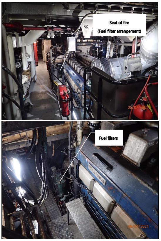
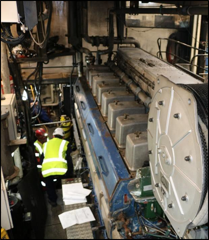
- Fire damage was contained to the engine room, which had sustained extensive heat and smoke damage to its upper parts. The damage was more extensive in the immediate vicinity of the low-pressure fuel filter arrangement located at the forward port side of the main engine. Figure 6 includes a photograph (top) taken from where the chief engineer was standing when first entering the engine room and observing flames. Note the minimal damage in the foreground, which was limited to smoke damage around deckhead (nautical term for ceiling) level.
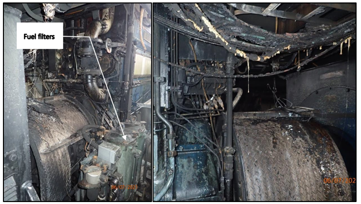
- Heat had caused extensive damage to plastic fittings and electrical cabling near the deckhead of the main engine compartment, more concentrated at the forward end of the engine room, above the seat of the fire (see figure 7).
- When the main engine is running, low-pressure fuel circulates through the fuel filter arrangement to the injector pumps on the main engine. The injector pumps deliver the fuel at high pressure to their respective engine cylinder. Any fuel not picked up and delivered by the injector pumps returns to the fuel service tank and then back through the filters in a continuous loop.
- Two accumulators are fitted to the fuel filter arrangement: one to the line supplying fuel to the main engine and one to the return fuel line. Their purpose is to absorb any fuel pressure shock loading (pulsing) created by the action of the injector pumps.
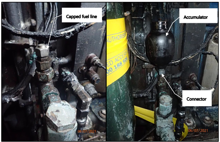
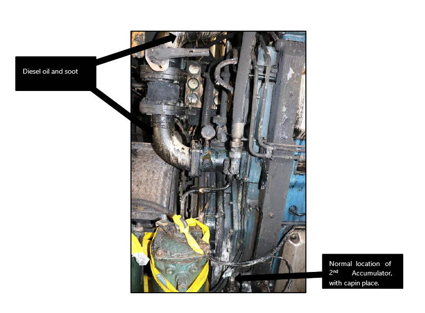
- As mentioned, after the crew had extinguished the fire they found the accumulator that was normally fixed on the supply line was missing. They found it lying on the tank top directly below where it should have been fixed (refer to figure 8).
- The other accumulator on the return line was still in place. It was found to be supported by a bracket designed to protect it against vibration, which would have also prevented it from unwinding from its fitting. There was no evidence of a similar support bracket having been fitted to the supply line accumulator at the time it became detached.
- Service records show that the detached accumulator was supplied and fitted on 25 May 2021 when the vessel was in Dunedin before departing on the accident voyage. The old accumulator had been sent ashore to a hydraulics contractor for servicing, but was found to be unserviceable. According to Talley’s they instructed the contractor to replace it with a new accumulator. The hydraulics contractor supplied a replacement accumulator and a connector for attaching to the fuel line.
- No information on the history of this replacement accumulator was available. It had been located in the hydraulics contractor’s inventory several years earlier, but the contractor had moved premises and introduced a new inventory control system. The replacement accumulator was brought across from the old premises, but was not entered into the new inventory system. It had a manufactured date of 2006 stamped into its steel casing.
- The hydraulics contractor supplied a new connector compatible with the accumulator and the fuel pipe on the vessel. The new connector was fitted to the replacement accumulator at the contractor’s workshop ashore. The contractor then fitted this assembly to the fuel pipe in the engine room.
- After the fire, the replacement accumulator that had detached was retained by the crew. The Commission later took possession of it for examination and testing. The old replaced accumulator was also recovered from the hydraulics contractor in Dunedin. Both accumulators were sent to a metallurgist for examination.
- The fuel pipe that had been repaired shortly before the fire was also removed and retained by the Commission. This pipe was also sent to the metallurgist for examination.
Tests and research
The repaired fuel pipe
-
The full metallurgist report is given in appendix 3. The report concluded (in part) the following:
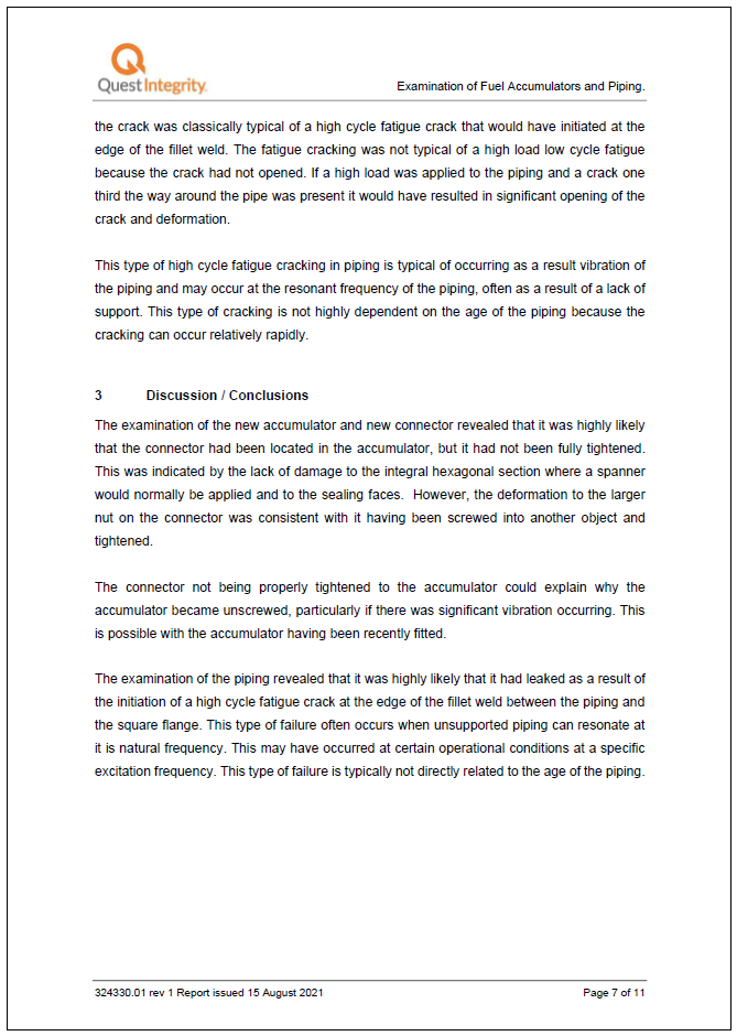
The examination of the piping revealed that it was highly likely that it had leaked as a result of the initiation of a high cycle fatigue crack at the edge of the fillet weld between the piping and the square flange. This type of failure often occurs when unsupported piping can resonate at its natural frequency. This may have occurred at certain operational conditions at a specific excitation frequency. This type of failure is typically not directly related to the age of the piping.
Accumulators
- The full metallurgist report is given in appendix 3. The report concluded (in part) the following:
Accumulator
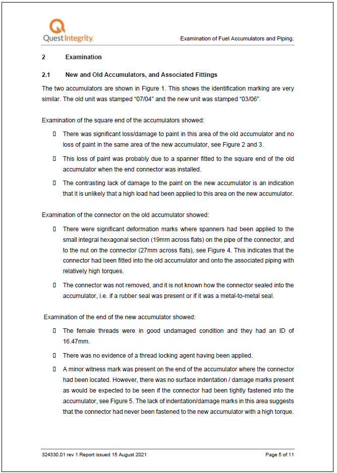
The female threads were in good undamaged condition and they had an [internal diameter] of 16.47mm.
There was no evidence of a thread locking agent having been applied.
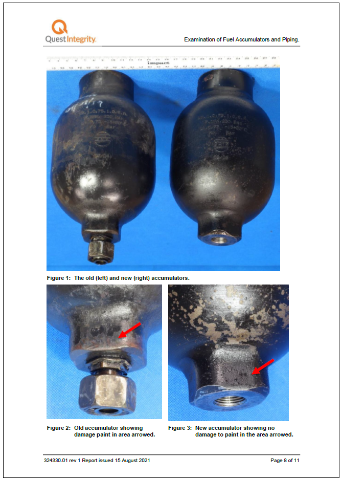
A minor witness mark was present on the end of the accumulator where the connector had been located. However, there was no surface indentation/damage marks present as would be expected to be seen if the connector had been tightly fastened into the accumulator.
Connector
The male threads of the new connector, that had become unscrewed prior to the fire, were in an undamaged condition and had an [outside diameter] of 17.75mm.
There was no evidence of a thread locking agent being applied to the male connector threads.
The male end of the connector was screwed into the female end of the new accumulator. They were a good fit, consistent with matching threads that were correctly machined. The connector could be very easily screwed in or out, i.e. with a very low torque.
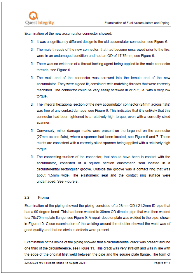
The integral hexagonal section of the new accumulator connector (24mm across flats) was free of any contact damage, see Figure 6. This indicates that it is unlikely that this connector had been tightened to a relatively high torque, even with a correctly sized spanner.
Conversely, minor damage marks were present on the large nut on the connector (27mm across flats), where a spanner had been located. These marks are consistent with a correctly sized spanner being applied with a relatively high torque.
The connecting surface of the connector, that should have been in contact with the accumulator, consisted of a square section elastomeric seal located in a circumferential rectangular groove. Outside the groove was a contact ring that was about 1.5mm wide. The elastomeric seal and the contact ring surface were undamaged.
- The metallurgist’s observations are discussed in the analysis of this report.
Bench testing of accumulator and repaired fuel pipe
-
The replacement accumulator, its new connector and the repaired fuel pipe were taken to an independent hydraulics workshop for further examination and testing. The purpose of these tests was to:
1. establish whether the repair to the fuel pipe was successful, and
2. establish at what point during the accumulator unscrewing from its connector would the connection begin to visibly leak marine diesel oil.
- The repaired fuel pipe was installed on a testbed filled with marine diesel oil and subjected to 10 bar pressure. The fuel pipe did not leak.
- The connector for the accumulator was fixed to the testbed and the accumulator screwed down on to the connector (see figure 9). The hydraulics expert noted that it was a ‘loose fit’ between the male thread on the connector and the female thread in the accumulator. The loose fit allowed considerable lateral play between the two components until the steel-on-steel mating between the two was achieved.
- The connector thread was identified as M18 x 1.5 pitch (M18 refers to the nominal diameter in millimeters and 1.5 pitch means there is 1.5 millimeters from thread to thread) with a flat face O-ring. The hydraulics expert considered the connector thread to have been machined at the lower (smaller) end of the allowable range, but within tolerance.
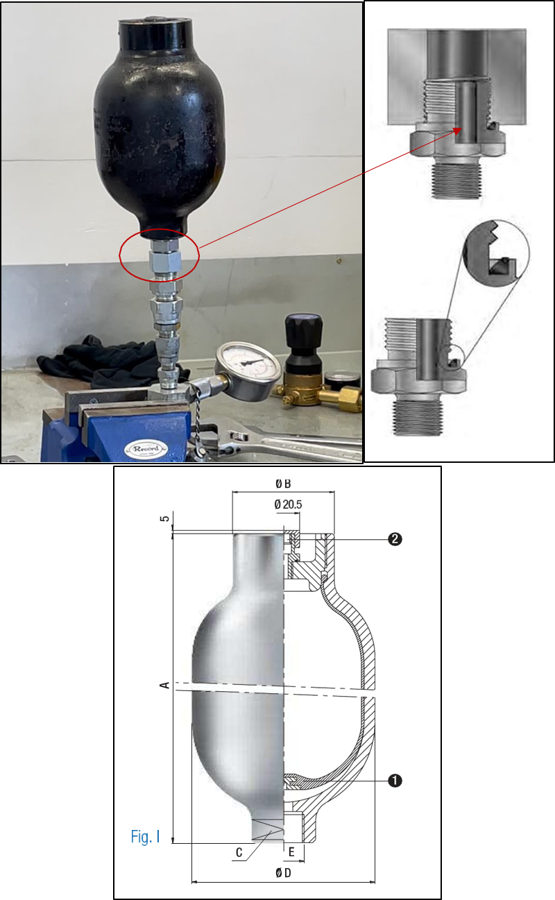
- The accumulator was screwed onto the connector and made hand tight only. The connection was then subjected to 10 bar pressure. The connection did not leak. The accumulator was then unscrewed a one-quarter turn. The marine diesel oil began flowing freely from the connection when reaching about 2 bar pressure. The accumulator was then screwed down a 1/8th turn (i.e., a1/8th turn unscrewed from hand tight). Marine diesel oil dripped from the connection when the accumulator was rocked side to side made possible by the tolerance between the two threads.
Fire investigation
-
The Commission engaged a fire investigator to assist in determining the cause of the fire. A copy of their full report is included as appendix 2. The fire investigator concluded (in part):
The point of origin [of the fire] was identified and confirmed as within the area of the [exhaust] manifold end box.
The accumulator has detached from its pipework and diesel oil spray resulting from the open connection has sprayed onto surfaces above, including the [exhaust] manifold cap. It is most likely that some of this diesel oil has come into direct contact with the hot exhaust manifold, exhaust pipework and/or clamps. A small inspection flap at the forward end of the engine was found unsecured and would have allowed diesel oil to enter the area housing the exhaust manifold.
The flame had travelled all the way back to the open connection feeding the missing accumulator.
The cause of the fire is believed to be the hot surface ignition of diesel oil which was spraying from an open pipe where an accumulator has detached from its normal mounting position.
Other relevant information
Fixed engine room Halon gaseous fire-extinguishing system
- The Amaltal Enterprise was fitted with a fixed Halon gaseous fire-extinguishing system for supressing fire in the engine room. The crew did not activate the system when fighting the fire. They said they did not think it was necessary because other measures they had taken had quickly brought the fire under control. A description of the system is included because there was some risk that it would not have delivered sufficient Halon into the engine room after the initial fire, had the crew needed to use it.
- The system comprised four independent Halon-filled pressure cylinders, three located in the main engine room (the space they are designed to protect) and one in the steering gear flat for protecting the emergency generator room. Upon activation each bottle in the engine room releases Halon directly into the space where they are located.
- The system was electrically activated from a control panel on the bridge. Opening the door to the control panel initiates two automatic functions: shutdown of any fans supplying or extracting air to and from the engine room; and a distinctive alarm sounding in the engine room to alert any crew to immediately vacate the space.
- Each Halon bottle has a discharge assembly fitted to the top of the bottle, incorporating a 24-volt direct current (DC) solenoid. The solenoids are wired in parallel back to the control panel. When the Halon system is activated, the solenoids are energised, resulting in the release of Halon from three bottles directly into the engine room or one bottle directly into the refrigeration plant room (see figure 10).
- There is also a pressure sensor within each discharge assembly, which are all wired in series back to the control panel. A drop in pressure in any one of the bottles will be detected and an alarm activated in the control panel on the bridge.
- Post-fire inspection revealed heat damage to the insulation shrouding the 24-volt cables leading to the release assembly on two of the Halon bottles. The most severe damage was to the cables on the bottle located in the immediate vicinity of the seat of the fire. It was not possible to test the function of the Halon system for health and safety reasons and due to the extensive damage to electric cabling within the engine room.
- Maritime Rule Part 40D – Design Construction and Equipment – Fishing Ships (Maritime Rules Part 40D –Design, Construction and Equipment – Fishing Ships, Appendix 2 – Fire Fighting Appliances, 2.1 – Ships 60m or more in length that proceed beyond restricted limits) came into force on 1 February 2000. The Amaltal Enterprise was built in 1988 and was first registered as a New Zealand vessel on 21 December 2000. Rule Part 40D (clause 40D.64 and Clause 2.1 of Appendix 2 of Maritime Rules Part 40D) required that the Amaltal Enterprise’s engine room be protected by either a pressure water spraying system, or a gaseous fire-extinguishing system, or a high-expansion foam system. Whichever system is installed it had to be compliant with the standards given in Maritime Rule Part 42B – Safety Equipment – Fire Appliances Performance Standards.
- However, at the time the Amaltal Enterprise was registered, Rule Part 42B was not yet in force. Part 42B was signed into law by the Transport Minister on 18 December 2000, but did not enter into force until 1 February 2001, one year after Rule 40D came into force and five weeks after the registration of the Amaltal Enterprise. Part 42B replaced the standards made under the Shipping (Fire Appliances) Regulations 1989 (these performance standards were published as a supplement to the New Zealand Gazette of 26 October 1989 (issue number 190) dated 31 October 1989). Accordingly, the standards that applied to the Amaltal Enterprise’s fire appliances at the time of the vessel’s registration were as set out in the in the Fire Appliances (Code of Practice for Ships of Class X) Notice 1989 (the Notice) (clause 8(a)(ii) of the Fire Appliances (Code of Practice for Ships of Class X) Notice 1989).
- The Notice required the vessel’s fixed fire-smothering gas installation to comply with Clause 24 of the General Code (the General Code was The Fire Appliances (Code of Practice for General Requirements for Fire Appliances) Notice 1989). Clause 24(3) of the General Code required compliance with the performance standards (referred to in Clause 2 of the General Code. Clause 2) authorised the Minister to prescribe the performance standards by notice in the Gazette (the official newspaper of the New Zealand Government that contains official commercial and government notifications that are required by legislation to be published), which he did by issuing The Shipping (Fixed Gas Fire Extinguishing Systems) Notice 1989. This Notice required the storage pressure containers to be located outside the protected space (with some limited exceptions) (Clause 2(1) of the The Shipping (Fixed Gas Fire Extinguishing Systems) Notice 1989).
- The Amaltal Enterprise was fitted with a fixed gaseous Halon fire-extinguishing system. The Halon system was placed on the Amaltal Enterprise during its new build in 1988 in accordance with the standards of the relevant foreign maritime administration at that time.
- Rule Part 42B came into force on 1 February 2001, replacing the performance standards for fire appliances set out in the many Gazette Notices issued by the Minister under the legislation in force at that time. Part 42B references the IMO Marine Safety Circular MSC Circular 848 (8 June 1998) (MSC/Circ.848 – Revised Guidelines For The Approval Of Equivalent Fixed Gas Fire Extinguishing Systems, As Referred to in SOLAS 74, For Machinery Spaces and Cargo Pump Rooms) (MSC 848), which provided guidelines for fixed gaseous fire-extinguishing systems, such as the Halon system fitted to the Amaltal Enterprise. The MSC 848 allowed for the Halon bottles to be located throughout the engine room, but under a number of conditions (see appendix 1 for the full circular). One condition was that in the event of damage to the release mechanism to one Halon bottle, “at least five-sixths” of the required amount of Halon gas could still be discharged into the engine room.
- The guidelines were amended in 2008 through MSC1/Circ.1267. That requirement was reworded to require that at least the amount of Halon needed to achieve the minimum extinguishing concentration could still be discharged into the engine room.
- The amount of Halon required for a space was derived from a formula fundamentally based on the volume of the space to be protected. The calculated volume of the Amaltal Enterprise’s engine room was 792 cubic metres, which meant 220 kilograms of liquid Halon was required to protect the space (referenced from the Halon General Arrangement Plan (100.87.224-0)). The 220 kilograms of Halon was stored in the three Halon bottles mentioned (about 73 kilograms per bottle). No reserve was provided in the event that one or more bottles failed to release due to damage by fire, explosion or other means.
Analysis Tātaritanga
Introduction
- A high percentage of shipboard fires originate in engine rooms. These spaces usually contain several fuel-fed internal combustion engines and ancillary equipment, which makes the engine room an inherently high fire risk compartment. Good design and maintenance is key to managing the risk of engine room fires. If a fire occurs, the consequences are managed by mandatory portable and fixed fire protection systems. Also, crew are required to be trained in fighting fires. Procedures that form part of safety management systems are developed for crew to follow in response to a fire.
- The crew response to this fire generally followed good industry practice and resulted in it being quickly brought under control. As always, however, there are lessons that can be drawn and applied to the industry to help manage the risk of fire on board ships in future.
- The following section analyses the circumstances surrounding this fire. Factors have been identified that increased the likelihood of the event occurring or increased the severity of its outcome. It also examines any safety issues that could have an adverse effect on future operations.
How the fire occurred
- The spread of diesel oil and burn patterns from the fire directly above the fuel filter arrangement supports the hypothesis that the accumulator had separated from its threaded connection, allowing diesel oil to coat the structure and pipework above that point.
- There are many potential sources of ignition in an engine room, particularly around operating machinery. Consequently, it could not be determined with certainty what provided the ignition source for the fire.
- That said, exhaust manifolds are a prime source of ignition due to their high temperature (typically about 350ºC for the Amaltal Enterprise’s main engine). The ignition temperature of diesel oil ranges between 230ºC and 256ºC (Fire Investigation Report (citing Babraukas, 2003)). Exhaust gases leave the engine via pipes from each cylinder and then enter the exhaust manifold, which runs along the top of the engine. The manifold was covered with a heat shield to provide protection against fire and prevent injury. The heat shield typically reaches temperatures between 70ºC and 80ºC
- There is a small inspection flap on top of the forward end of the main engine, immediately above the fuel filter arrangement. Its purpose is for protecting a small gap between the heat shield around the exhaust manifold and the engine cylinder heads. This flap was located within the area coated by diesel oil spraying from where the accumulator had been located. The flap was not secured and would have been a point where oil could enter the exhaust manifold space. Therefore, it is about as likely as not the main engine exhaust manifold was the source of ignition for the marine diesel oil.
- The fire almost certainly began when marine diesel oil from the main engine low-pressure fuel system escaped under pressure when the accumulator dislodged from its fuel pipe. At a typical operating pressure of 8 bar, diesel oil has sprayed upwards, spraying the deckhead above and then dropping down over the main engine and alternator below.
The accumulator
Condition of the accumulator
- The accumulator that dislodged from its fuel pipe was not new. Its steel casing had been manufactured in 2006, but little is known of its service history other than it was ‘used’ inventory that had not been entered into the supplier’s recently introduced inventory system.
- The accumulator works by charging the rubber bladder with nitrogen gas to a pressure compatible with the pressure of the low-pressure fuel system. Any pressure in the fuel system will compress the bladder from the bottom until the pressure in the bladder is equal to the pressure in the fuel line. If the pressure in the fuel line fluctuates then the rubber bladder flexes in response, therefore acting as a form of shock absorber.
- When the accumulator was dismantled, it was found that the rubber bladder had split circumferentially around the lip at the top where it sealed onto the end cap. It could not be determined exactly when the split had occurred. The accumulator had been installed in Dunedin at the beginning of the voyage about five weeks earlier. The hydraulics contractor who supplied and fitted the accumulator said they had charged the bladder with nitrogen gas and checked that it was holding its charge before fitting it on board. The accumulator would not have held its charge if the bladder had been split at that time. It is therefore very likely that the bladder failed while in service during the accident voyage.
- The bladder was manufactured in 2004, meaning it was about 17 years old, two years older than the casing in which it was installed. As mentioned, the service history of the bladder is unknown. It is possible that it had remained idle for a prolonged period. The manufacturer’s instruction is that lubrication must be applied between the bladder and the steel casing when replacing the bladder or if the accumulator had been idle for a prolonged time. The hydraulics contractor did not lubricate inside the accumulator before fitting it on board the Amaltal Enterprise.
- There was nothing in the manufacturer’s maintenance and installation manual to indicate how often the bladders should be changed. The hydraulics contractor opined that for this type of installation they were replaced when they failed. The fact that the bladder was stamped with a manufactured date would indicate that the age of a bladder had significance. The manufacturer advised that there is no exact recommended interval for replacing the bladder of an accumulator because its life depends on too many factors beyond their control, such as (but not limited to):
- compatibility of the working fluid with the bladder material
- correct pressure and temperature ranges
- correct pre-charge pressure of the accumulator
- presence of contaminants in the fluid
- pressure and/or temperature fluctuations
- regular maintenance intervals.
- With the internal bladder having failed the accumulator would not have been performing as designed. Marine diesel oil would have invaded the entire cavity, including inside the bladder. The accumulator would then have been subjected to any pulsing in the fuel system, a phenomenon it was installed to absorb.
- The condition of the thread on both the accumulator and the male fitting of its connector was observed to be good. There was no observable damage to the threads on either, meaning it was virtually certain that the accumulator had unscrewed from its connector, rather than it having been forced off under pressure.
Dislodging of the accumulator
- From the crew’s account of events the work on the repaired fuel pipe was completed, the area cleaned, the fuel system pressurised and checked for leaks, and then the main engine was restarted. Within about 50 minutes, the accumulator had unscrewed completely and fallen to the tank top below, escaping fuel had ignited, and these conditions had caused a main engine alarm to activate.
- The accumulator that dislodged was located in the immediate area where the crew had been working. Their focus and attention would have been on the fuel pipe that had just been repaired and refitted. They would have had little idea that the accumulator located immediately above and to the left of this repaired fuel pipe was about to become an issue. Nevertheless, a major leak should have been obvious to them, a minor leak perhaps less so. It is therefore about as likely as not that the accumulator was not leaking when they left the engine room. The reasons for this are discussed in the following sections.
- The accumulator had been fitted to the fuel system more than five weeks prior to it becoming dislodged. The crew said that they had carried out no work on the accumulator since it was fitted. The following analysis is made on that premise.
-
The Commission considered several possible factors that singularly or in combination caused the accumulator to unwind and dislodge.
A lower-than-normal torque was applied when fitting the connector into the accumulator at the hydraulics contractor’s workshop before the assembly was fitted on board.
Forced vibration and resonance created by the machinery and propulsion system in the engine room have caused the accumulator to lose the steel-on-steel surface contact with its connector.
The observed ‘loose fit’ between the male thread on the connector and the female thread of the accumulator once the steel-on-steel connection between the two components was lost allowed lateral play between the two, making the assembly more susceptible to vibration and affording little resistance to prevent the accumulator from unscrewing.
Failure of the bladder within the accumulator meant the assembly was susceptible to pressure pulsing within the fuel system rather than absorbing these forces as it was installed to do.
The accumulator was not fitted with a supporting bracket or any other means of preventing it from unwinding.
Fitting the accumulator
- The hydraulics contractor who fitted the connector into the accumulator was confident that normal torque had been applied to tighten the connector to the accumulator. The contractor described placing the square end of the accumulator in a vice and using an open spanner to tighten it. A torque wrench was not used because these are not readily available for open-end spanner applications. The contractor was an experienced hydraulics engineer and used that experience to judge the torque needed to obtain a good tight connection.
- For the type of connector used the seal is not provided by the steel-on-steel face, but instead by the encapsulated elastomeric (compound that has rubber-like properties) O-ring. The liquid in the pipe forces the O-ring on to the steel face of the accumulator. The higher the pressure in the pipe, the more effective the seal. The steel-on-steel face between the connector and the accumulator need only be tight enough to prevent the O-ring bursting out of its cavity and to prevent the accumulator from unscrewing (refer to figure 8).
- The metallurgist engaged by the Commission opined that it was highly likely that the connector had not been fully tightened into the accumulator before the assembly was fitted on board. This hypothesis was based on two observations: first, the lack of damage to the smaller (24 millimetre) integral hexagonal section of the connector; and second, the absence of damage to the O-ring and the metal ring on the connector that would normally be in contact with the accumulator.
- The metallurgist noted the slight damage evident on the larger (27 millimetre) nut of the new connector (the end that connected the assembly to the fuel pipe) and correlated this to the lack of similar damage on the small nut. They therefore concluded that the small nut had not been fully tightened into the accumulator. The metallurgist also noted the significant damage to the nut on the old connector that was fitted to the old, discarded accumulator and similarly correlated this with the lack of similar damage on the new connector, with the same conclusion that the new connector had not been fully tightened (see appendix 3).
- However, the amount of damage inflicted on a hexagonal nut will depend on several factors:
- how often it has been tightened or loosened
- what type, quality and compatibility of the spanner used each time
- how much force has been applied on each occasion to tighten it, as well as how much is required to loosen it
- at what angle to the hexagonal plane the spanner was used on each occasion.
- As mentioned, achieving a seal between the newly supplied accumulator and its new connector did not rely on a particularly high torque. However, the connector on the old, discarded accumulator was different. It had a different style of seal; one that relied on a tight mating between the connector and the accumulator through a metal washer. There was no elastomeric O-ring. This connector would have required a higher torque to achieve a seal than the new connector that was supplied with the new accumulator. Also, it was old and little is known of its history. Therefore, comparing the condition of these two hexagonal nuts provides little useful basis for the hypothesis that the new connector was not fully tightened into the accumulator.
- Similarly, comparing the condition of the small and large hexagonal nuts on the new connector provides little support to the hypothesis. The smaller end of the connector that inserted into the accumulator had a different type of seal than the large nut that fitted to the fuel pipe on board. The smaller end of the connector was fitted to the accumulator in the workshop with the accumulator clamped in a vice. The accumulator/connector assembly was then fitted to the fuel pipe on board with a larger spanner. The absence of damage on the small end of the connector could simply be explained by the circumstances of the two fitments being different.
- In summary, it has not been possible to establish how tightly the connector was fitted to the accumulator in the Dunedin workshop. This is particularly so when considering the other potential factors discussed in the following sections, and the fact that the connection is said to have maintained its integrity for about five operational weeks at sea before the accumulator dislodged.
Vibration and resonance
- Left in free vibration (the type of vibration in which a force is applied once and the structure or component is allowed to vibrate at its natural frequency. Source: Collinsdictionary.com (February 2022)) a system or component will always vibrate at its natural frequency. Forced vibration is a type of vibration in which a force is repeatedly applied to a mechanical system or component (Source: Collinsdictionary.com (February 2022)). If the forced vibration is different from the natural frequency of the component, then the amplitude of such vibrations is usually small. Resonant vibration is forced vibration in which the frequency of the disturbing force is very close to the natural frequency of the system or the component (source: McGraw-Hill Dictionary of Scientific & Technical Terms (6E Copyright© 2003) by The McGraw-Hill Companies, Inc.). When resonant vibration occurs the amplitude of vibration is very large and potentially more destructive.
- Forced and resonant vibrations in an engine room can be problematic. There are many potential sources of vibration from operating systems: combustion engines, pumps, compressors, gearboxes and propellers, to name a few. Some potential effects of vibration are the loosening of components, chafe or wearing, cracking and (in extreme cases) destruction if resonant vibration is present and allowed to prevail. Components, particularly safety-critical components, are usually clamped or supported to dampen or guard against the effects of vibration. Clamping of the accumulator is discussed in the following sections.
- Because the Amaltal Enterprise was in port undergoing an extensive refit following the fire, it has not been possible to replicate the state of vibration around the fuel filter arrangement where the accumulators were located. Of note, however, was that one end of the fuel pipe to which it was fitted was clamped to the solid ship structure and the other directly to the main engine. The main engine was mounted on resilient chocks, which were designed to allow the engine to flex independently of the ship’s structure. This arrangement was a potential source of vibration and stress on the pipe and the accumulator assembly. It would have been good engineering practice to incorporate a flexible section of fuel hose between the engine and the fuel filter arrangement to alleviate this potential source of stress on the system’s components.
- It is virtually certain that the fuel filter arrangement was to some degree subjected to vibration during normal operation, and that any vibration could potentially have contributed to disestablishing the steel-on-steel contact between the accumulator and its connector, and/or accelerated the process of it unscrewing and dislodging. However, we cannot say how much of a factor it was. It would depend on the other circumstances discussed in this section.
Loose fit between threads
- As mentioned, there was a loose fit between the male thread of the connector and the female thread on the accumulator. The difference in the two threads is considered within acceptable tolerances and is the result of matching components from different manufacturers who machine their components to slightly different tolerances. The result was noticeable lateral play between the two components. However, the lateral play was prevented when the connector was tightened into the accumulator and the steel-on-steel mating between the two components was achieved.
- The threads on both components being undamaged is a further indicator that both had been manufactured within acceptable tolerances. However, the lateral play meant that when the steel-on-steel mating was lost as the accumulator began unscrewing from its connector, the accumulator would have been more prone to any vibration and there was very little resistance to it unscrewing. For this reason, it is likely to have been a factor contributing to the accumulator dislodging.
Failure of the bladder
- As mentioned, it is very likely the bladder failed during the accident voyage. Before it failed it would have occupied most of the internal cavity of the steel housing, charged with nitrogen gas at about 4 bar pressure, and would have been absorbing the fluctuations in fuel pressure (pulsing) caused by the action of the fuel injector pumps. Once it failed diesel oil would have invaded the entire cavity, displacing the nitrogen gas. From that point the accumulator and its connector would have been subjected to the pulsing in the fuel system rather than protecting against it. It is possible that pulsing in the fuel system assisted in the accumulator unscrewing, particularly when the steel-on-steel face between the accumulator and its connector was lost and it then became more prone to vibration as well.
- The bladder developed circumferential tears around the top lip close to where it sealed around the top cap. According to its date stamp it was about 17 years old. Given the lack of service history prior to it having been fitted, it would have been good engineering practice to have replaced it with a new one before putting the accumulator back in service, or at least removed, inspected and lubricated it in accordance with the manufacturer’s recommendations.
Support bracket
- There were several other accumulators fitted around the Amaltal Enterprise’s machinery spaces. Most were supported by a bracket to guard against vibration. The two accumulators fitted to the fuel filter arrangement weighed about 5 kilograms, which if left unsupported and subjected to vibration would cause adverse stresses on the vertical fuel pipes to which they were fitted, including their connectors.
- The other accumulator fitted to the fuel filter arrangement was fitted with a supporting bracket, which served a secondary purpose of preventing the accumulator from rotating (unscrewing from its connector). As mentioned, the accumulator that dislodged was not fitted with a supporting bracket at the time of the accident. Talley’s confirmed that such a bracket had been fitted in 2015, but they had no record of when it had been removed. The old, discarded accumulator bore the marks on its steel casing consistent with a support bracket having been fitted at some time.
- It would have been good engineering practice to have fitted a support bracket to the accumulator. It is virtually certain that had one been fitted the accumulator would have been prevented from unscrewing and the fire would not have occurred. A support bracket would have been the last defence in the system – a safeguard against the other potential contributing factors discussed above.
Engine room exhaust fan
- The No. 2 exhaust fan for the engine room had shut down when the Amaltal Enterprise blacked out, but it operated again when the emergency generator auto-started in response to the black out. The running fan hampered the crew’s efforts to shut down the engine room and starve the fire of air. We discuss why this occurred because its failure to shut down could potentially have worsened the consequences of the fire.
- The emergency power supply to the No. 2 exhaust fan was from the emergency generator switchboard located in the emergency generator room. This was a design feature that would provide a means of mechanically ventilating the engine room if power from the main switchboard was not available. The circuit breaker that protected the power supply to the No. 2 exhaust fan could also be remotely tripped by activating an electromagnetic coil called a ‘shunt trip’ accessory fitted to the circuit breaker. Normally, this shunt trip would mechanically trip the circuit breaker when it was energised by the remote switches on the bridge.
- On the Amaltal Enterprise, power to the shunt trip could be applied from the bridge by either pushing the emergency stop buttons or opening the Halon cabinet door (as described in paragraph 2.58). Either action should have activated the shunt trip coil and tripped the exhaust fan circuit breaker, stopping the fan. The crew tried both methods, but the fan continued to run.
- During the refit of damaged electrical systems in Nelson it was found that the shunt trip coil windings in the No. 2 ventilator fan circuit breaker had burnt out, rendering it unserviceable. This was the reason why neither action taken by the crew stopped the fan. The fan stopped only when the chief engineer went to the emergency generator switchboard and manually tripped the circuit breaker.
- Testing of remote trips is undertaken periodically as part of planned maintenance/checks conducted by crew, and these devices are also tested periodically in the presence of surveyors. It could not be established when the coil winding in the shunt trip had burnt out. The design of the electrical systems on board the Amaltal Enterprise was such that when the remote trip switches are closed (pushing the remote stops or opening the door on the Halon cabinet), the shunt trip coil is energised for a short period of time to activate the mechanical trip mechanism. If the coil remains energised due to a mechanical fault with the coil or the trip mechanism, it can potentially cause the shunt trip coil to overheat and burn out. This would not necessarily become apparent until the remote trip function was tested or activated in an emergency, as in this case. The shunt trip was replaced during the post-fire refit.
Maintenance
Safety issue: The process for supervising and controlling maintenance conducted by shore contractors during the port turnaround in Dunedin did not adequately manage the risk of what could happen if systems are left in an unsafe state.
- The system for programming maintenance on board Talley’s vessels during port turnarounds was robust enough and in general the Amaltal Enterprise had the appearance of a well-maintained vessel.
- The Amaltal Enterprise spent long periods (about six weeks) at sea fishing. Maintenance that cannot be performed at sea is programmed for the relatively short turnarounds while the vessel is in port discharging its product and replenishing for the next voyage. A variety of contractors are used to complete the agreed work. Most of the crew usually change during this busy period, adding to the complexity of the port stay.
- The turnaround in Dunedin before the accident trip was typical of this process. Leaving aside the question of whether the new accumulator was properly installed, the process that was followed lacked rigour. The engineering staff who were leaving the vessel briefed the hydraulics contractor on the task, and they were then essentially left unsupervised to remove it, the ship’s staff having depressurised the fuel system. There was a delay in completing the task because the old accumulator was deemed unserviceable and a replacement was sourced from the contractor’s stock. However, a connector that was compatible with both the replacement accumulator and fuel pipe to which it would be fitted had to be sourced from Auckland.
- By the time the replacement accumulator and the new connector were ready for fitting on board, the engineering staff who had just joined the vessel had taken on the responsibility for the task. The contractor fitted the accumulator, advised the engineers that they had done so and departed the vessel. The fuel system was not then tested until the main engine was being readied for sea. The process did not include the following checks:
- a check to ensure the fuel system was depressurised before work began
- a check and sign-off that the task had been satisfactorily completed
- a check that the system was intact and operating correctly.
- The Commission has made a recommendation to address this safety issue (see section 6).
Response to the fire
- As mentioned, the crew’s response to the fire generally followed good industry practice. However, there are a number of lessons that can be drawn from the response.
- A good response to a fire is one where: everyone is alerted to the fact; everyone is accounted for; crew assemble in their assigned fire parties at their designated stations; and good communication is established between all fire parties.
- The chief engineer was knowledgeable about what needed doing to close down the engine room and immediately began working through the tasks. However, he was doing so without having reported to an emergency assembly point and had no means of communicating directly with the other parties. The designated assembly point for engineering staff was the engine control room, which due to the location of the fire was not an option. The risk of not reporting to an alternative assembly point was that if something untoward happened to the chief engineer (or others had adopted a similar approach), and the fire then rapidly became uncontrollable, then the required command and control structure to fight the fire would be incomplete.
- Fortuitously, other crew members assembled at their stations and made preparations to fight the fire, and the actions of the chief engineer were successful in preventing it escalating out of control. The engineering staff later reported to an alternative assembly point and reported their headcount to the bridge. However, there was some delay in completing the headcount and it was not complete. With a crew of 45 it would be easy for someone to be in danger and missed. As it was, the first mate was sleeping and had not been aroused by the fire alarm. The first mate’s absence went unnoticed until the skipper wanted to communicate and realised they had not been seen.
Halon system
Safety issue: The Halon bottles for the fixed Halon gaseous fire-extinguishing system were located in the machinery spaces, the spaces they were designed to protect. If one or more bottles were disabled because of the fire, the calculated amount of Halon gas to extinguish a major fire would not be available.
- The fixed Halon gaseous fire-extinguishing system on board the Amaltal Enterprise was not used to fight the fire. The crew decided not to activate it because they felt they had the fire under control. This appeared to have been a reasonable decision based on the outcome. They did have the fire under control at the time and eventually succeeded in putting it out.
- This decision, however, brought with it a degree of risk. Shipboard fires can escalate from being under control to uncontrolled in a very short time. Fixed gaseous fire-smothering systems, where the gas is stored outside of the engine room, can of course be used at any stage of the firefighting response. However, for systems like that on the Amaltal Enterprise, where the gas is stored in the space that is on fire, the risk of the system being rendered partially or fully unserviceable increases with time. We were unable to determine how serviceable the Halon system would have been if the crew had later needed to use it. If just one of the three Halon bottles could not be released, it is unlikely there would have been sufficient Halon to achieve the ideal fire-smothering required for a more serious fire.
- The vessel had to comply with Rule Part 40D, which required the fitting of a fixed engine room fire-smothering system that met the performance standards prescribed in Rule Part 42B. Yet, Rule Part 42B did not come into force until one year after Rule Part 40D came into force, during which period the Amaltal Enterprise became registered as a New Zealand ship. As Rule 42B was not applicable because it had not entered into force, then the performance standards set out in Gazette Notices issued under the Shipping (Fire Appliances) Regulations 1989 applied. Regardless, the Halon system was not compliant with either performance standard as both specifically prohibit having the Halon bottles located in the engine room – to manage the risk of the system being compromised by any fire it was installed to combat.
- There were many vessels worldwide that used Halon systems where the bottles were located in the engine room. In 1998, the IMO recognised the risk and issued guidance in the form of a Marine Safety Circular (MSC 848). The circular imposed several conditions to mitigate the risk. One condition was that sufficient Halon must be carried so that if the release mechanism for one Halon bottle is damaged, then at ‘least five-sixths’ of the required amount of Halon gas could still be discharged into the engine room. In 2008, the IMO amended that condition to require that the minimum extinguishing concentration in the space can still be discharged into the engine room if one Halon bottle is damaged. MSC848 is incorporated into the Maritime Rules by way of reference in Part 42B.22(2).
- It is unclear why the Halon system, despite being non-compliant, was approved by the Lloyds Classification Society (Lloyds) who were the ‘recognised organisation’ acting on behalf of Maritime New Zealand (MNZ).
- Talley’s were unaware that the Halon system was not compliant, having relied on the process of MNZ and Classification Society certification. Talley’s have now elected to replace the Halon system with a modern equivalent that complies with current maritime rules. However, due to supply logistics the new system was not available for fitment during the refit following the fire. Their intention is to install the new system after July 2022 when all the components have been received.
- The Commission has made recommendations for ensuring that this is undertaken and managing the risk in the interim (see section 6 of this report).
Findings Ngā kitenge
- It was virtually certain that the source of fuel for the fire was marine diesel oil that escaped under pressure when an accumulator in the low-pressure fuel system unwound from its pipe connector and dislodged.
- It is about as likely as not that heat from the main engine exhaust provided the ignition for the marine diesel oil.
- The threads on the accumulator and its connector were undamaged, meaning that the accumulator unscrewed from its pipe connector rather than having been forced off under pressure.
- It could not be established with any certainty what caused the accumulator to unscrew from its connector, but it is likely to have been any combination of the following conditions.
- A lower-than-optimal torque being applied when fitting the connector into the accumulator.
- Vibration created by the machinery and propulsion systems in the engine room.
- The ‘loose fit’ between the male thread on the connector and the female thread of the accumulator. Once the steel-on-steel connection between the two components was lost, lateral play between the two made the assembly more prone to vibration and afforded little resistance to the accumulator unscrewing.
- The failure of the bladder within the accumulator meant the assembly was susceptible to pressure pulsing within the fuel system rather than achieving its purpose of absorbing these forces.
- The accumulator was unlikely to have been fit-for-purpose when it was fitted on board the Amaltal Enterprise. This was because of the age of its internal bladder and no lubrication having been applied between the bladder and the steel casing following an undetermined period in storage.
- The accumulator was free to unscrew because it was not fitted with a supporting bracket or any other means of preventing it from unwinding.
- The engine room No. 2 exhaust fan, which initially stopped operating when the ship blacked out, automatically started running again when the emergency generator auto-started. This hampered the crew’s efforts to close down the engine room and deprive the fire of oxygen, and potentially increased the consequences of the fire.
- The engine room No. 2 exhaust fan failed to shut down when the crew activated the remote trips because the shunt trip coil winding on the electrical circuit breaker for the fan was burnt out. It could not be established when this fault had occurred.
- The firefighting response generally followed good industry practice and resulted in the fire being extinguished. However, there are lessons to be drawn to improve the standard of future emergency response.
- The crew’s decision to not activate the engine room fixed Halon gaseous fire-smothering system was reasonable under the circumstances. However, under different circumstances any delay in activating the Halon system risked it not being fully functional due to it being in the space it was designed to protect.
- The Halon system did not comply with the relevant New Zealand maritime legislation or IMO guidelines because it had insufficient redundancy if the fire had disabled part of the system.
Safety issues and remedial action Ngā take haumanu me ngā mahi whakatika
General
- Safety issues are an output from the Commission’s analysis. They typically describe a system problem that has the potential to adversely affect future operations on a wide scale.
- Safety issues may be addressed by safety actions taken by a participant, otherwise the Commission may issue a recommendation to address the issue.
Maintenance control
- The process for supervising and controlling maintenance conducted by shore contractors during the port turnaround in Dunedin did not adequately manage the risk of what could happen if systems are left in an unsafe state.
- No action has been taken to address this safety issue. Therefore, the Commission has made a recommendation in section 6 to address this issue.
Uncompliant fixed Halon gaseous fire-extinguishing system
- The crew’s decision to not activate the engine room fixed Halon gaseous fire-smothering system was reasonable under the circumstances. However, under different circumstances any delay in activating the Halon system risked it not being fully functional due to it being in the space it was designed to protect.
- The Halon system did not comply with the relevant New Zealand maritime legislation or IMO guidelines because it had insufficient redundancy if the fire had disabled part of the system.
Other safety action
- Participants may take safety actions to address issues that would not normally result in the Commission issuing a recommendation.
- On 7 July 2021, Talley’s issued a fleet memorandum outlining the incident and advising crews to undertake a number of checks associated with the low-pressure fuel systems, including ensuring accumulators are well secured.
- Talley’s now require that all accumulators fitted to its vessels be supported by a bracket.
- MNZ’s Rule Part 40 Series project team are conducting an in-depth evaluation of the regulatory settings for fire-fighting systems. This work includes consideration of appropriate performance and installation standards, how to regulate older systems, and which ships should be required to have on board fire-fighting systems. ”We believe that this work will help ensure that the rules are clear and fit-for-purpose, reducing the risk of similar issues arising in the future.”
- It is unclear whether this misapplication of the relevant legislation to the Amaltal Enterprise is an isolated case. However, the size of the New Zealand fishing fleet that could potentially be affected is small. The Commission welcomes this initiative by MNZ.
Recommendations Ngā tūtohutanga
General
- The Commission issues recommendations to address safety issues found in its investigations. Recommendations may be addressed to organisations or people, and can relate to safety issues found within an organisation or within the wider transport system that have the potential to contribute to future transport accidents and incidents.
- In the interests of transport safety, it is important that recommendations are implemented without delay to help prevent similar accidents or incidents occurring in the future.
New recommendations
- The Halon gaseous fire-extinguishing system on board the Amaltal Enterprise did not meet the IMO guidance for systems where the extinguishing gas is located in the space it is designated to protect. After the accident, the owner of the vessel has communicated that they intend to replace the Halon system with a modern equivalent that complies with current maritime rules. However, due to supply logistics the new system was not available for fitment during the refit following the fire. The replacement fire-smothering system is scheduled to be progressively fitted during the vessel’s port turnarounds after July 2022 when all of the components have been received.
-
On 25 May 2022, the Commission recommended that Maritime New Zealand ensure that as soon as reasonably practicable the owner of the Amaltal Enterprise install a new system that complies with current maritime rules and put in place additional measures to manage the risk created by the limitations of the current fire-extinguishing system until such time as the new system is installed. (009/22)
On 13 July 2022, MNZ replied:
Maritime NZ have provided the Commission with the following response to recommendation 009/22:
Maritime NZ accepts recommendation 009/22. We understand that Talley’s plans to replace the fire-fighting system in the very near future. We will consider whether any compliance action is necessary until the system is replaced. Once the system is replaced, we will encourage the operator to review their Maritime Transport Operator Plan and make any necessary amendments based on lessons learned from the incident.
In the longer term, Maritime NZ will continue to review the regulatory settings for fire-fighting systems as part of the 40 Series project. This work includes consideration of appropriate performance and installation standards, how to regulate older systems, and which ships should be required to have on-board fire-fighting systems. We believe that this work will help ensure that the rules are clear and fit-for-purpose, reducing the risk of similar issues arising in the future. We are also considering whether there are any lessons from TAIC Report MO-2021-202 in relation to our oversight of surveyors as third party regulators.
-
On 25 May 2022, the Commission recommended that Talley’s introduces a system for managing contractors working on board. The system should include sign-off for each task, a job safety analysis for each task that may pose risks to the contractors or crew and, where applicable, testing to ensure the repaired system is fit-for-purpose. (010/22)
On 10 June 2022, Talley’s replied:
Talley’s have provided the Commission with the following response to recommendation 010/22:
a) Talley’s have prepared a draft PCBU overlapping duties framework to manage contractors at layups and turnarounds, using the WorkSafe Good Practise Guideline PCBU’s working together document. In addition to this, Talley’s is engaging in detailed consultations with shore staff, vessel staff, contractors, and other stakeholders, outcomes of which will help us to understand where additional processes may be required to support their current processes.
b) On completion of the consultation process, guidance to support each step will be created and distributed to Talley’s staff, contractors and stakeholders, against which current activities can be benchmarked and modified if required.
c) It is anticipated that the draft framework document will be finalised by the end of June 2022 and the detailed processes by the end of July 2022.
d) Additionally, as part of their ongoing initiatives to reduce risk, each step in the turnaround/layup process has been reviewed, and updated documentation (worklists with contractor controls) and processes has been developed to manage all ongoing activities involving contractors on the vessels. Examples of this are:
- all contractors reporting to chief/2ND engineer when they come aboard and depart the vessel
- review of qualifications and competencies of staff who issue permits.
e) Finally, Talley’s are updating and continually modernising their PPM and maintenance systems. This includes the consideration of the implementation of a dedicated marine engineering software package (Marasoft) to assist in the managing of contractors working on board.
Key lessons Ngā akoranga matua
- It is important that repair and maintenance is performed under controlled conditions, and with appropriate procedures for tagging out, checking, testing and signing off each task, particularly when working on safety-critical systems.
- Forced and resonant vibration in engine rooms can be problematic. It is important that components are secured against vibration to guard against the loosening, chafe or wearing, cracking and (in extreme cases) destruction of components, particularly safety-critical components.
- It is important that power supply tripping devices that are designed for emergency situations are routinely tested to ensure they will function correctly during an emergency.
- When responding to an emergency it is crucial that crew fully consider the important elements of command and control, specifically, accounting for all personnel and establishing good communications.
- When a vessel has a fixed gaseous fire-extinguishing system, where the gas and associated release mechanisms are located in the space that they are designed to protect, it is important that crew understand that the longer they delay activation, the higher the risk that fire will render these systems partially or fully inoperable.
Data summary Whakarāpopoto raraunga
Details
Conduct of the Inquiry He tikanga rapunga
- On 3 July 2021, MNZ notified the Commission of the occurrence. The Commission subsequently opened an inquiry under section 13(1) of the Transport Accident Investigation Commission Act 1990 and appointed an Investigator-in-Charge
- The Amaltal Enterprise arrived at Nelson on the evening of 5 July 2021. On 5 July, the Commission issued a protection order over affected areas in the Amaltal Enterprise engine room, including the main engine low-pressure fuel system arrangement.
- Two Commission investigators attended the vessel on 6 July 2021 and over four days conducted an examination of the site and interviewed key personnel from the crew and Talley’s shore management. The Commission seized the accumulator and its connector, as well as a section of low-pressure fuel pipe that had been repaired shortly before the fire occurred.
- On 6 July 2021, the Commission engaged a specialist fire investigator to determine the origin and cause of the fire.
- On 19 July 2021, the Commission issued a seizure notice for, and took delivery of, the old accumulator that had been replaced in Dunedin.
- On 28 July 2021, a Commission investigator revisited the Amaltal Enterprise at Nelson to gather further evidence, after which the protection order placed over the components of the main engine low-pressure fuel system was lifted.
- On 29 July 2021, the Commission engaged an expert metallurgist to examine and report on the condition of the replaced and replacement accumulators and the repaired fuel pipe from the Amaltal Enterprise.
- On 24 September 2021, the Commission engaged a hydraulics expert to pressure/leak test the section of repaired low-pressure fuel pipe that had been removed from the Amaltal Enterprise.
- On 27 October 2021, the Commission engaged a hydraulics expert to conduct a series of tests on the replacement accumulator and its pipe connector.
- On 16 November 2021, two investigators travelled to Dunedin and interviewed personnel from the hydraulics contractor.
- On 21 March 2022, the Commission approved a draft report for circulation to nine interested persons for their comment. Submissions were received from five interested persons. Any changes as a result of those submissions have been included in the final report.
- On 25 May 2022, the Commission approved this final report for publication.
Glossary Kuputaka
- Aft
- At, near or towards the stern of a vessel
- Bar
- Unit of pressure – 1 bar is equal to 100 kilopascals (SI metric unit)
- Bow
- The front of a vessel
- Bridge
- The place on a ship from which the vessel is normally controlled
- Circuit breaker
- An electrical safety device designed to protect an electrical circuit from an overcurrent or short circuit.
- Damper
- A normally-open flap that can be released to close and seal an opening
- Deckhead
- Nautical term for ceiling
- Elastomeric
- Having a rubber-like quality
- Electromagnetic coil
- One or more circular turns or ‘windings’ in a current-carrying wire designed to produce a magnetic field.
- Free vibration
- The type of vibration in which a force is applied once and the structure or component is allowed to vibrate at its natural frequency
- Port
- The side of a vessel that is left when facing forward
- Starboard
- The right side of a vessel when the viewer is facing forward
IMO Guidelines for Fixed Gas Fire-Extinguishing Systems


Fire Investigation Report
FV Amaltal Enterprise
04/02/22
Description and Use
The Amaltal Enterprise is a 69m Factory Fishing Trawler built in 1988.
Pre-incident Events
At the time of the fire the ship was working off the West Coast nearing the end of its six-week trip. They had shut down their operation earlier in the day to repair a leak in a diesel oil pipe located below the diesel filters. This was repaired, cleaned up and thoroughly inspected following start up to ensure the repair was leak free. No other leak was detected during this inspection.
Discovery of Fire
A fire was discovered in the engine room of the ship after an “engine room alarm” activated in the engineer’s workshop. The Chief Engineer went to the engine room to investigate the alarm and upon entering saw what he described as a “geyser of fire” coming from the accumulator.
Fire Response
The ship’s crew instigated their firefighting plan and extinguished the fire before it was able to spread within the ship. An origin and cause investigation commenced on 8 July 2021 in Nelson.
Interviews
Formal interviews were conducted by TAIC staff, and the Chief Engineer and one other Engineer were available to assist with information during the investigation. Statements from all these sources inform this report.
Scene Examination
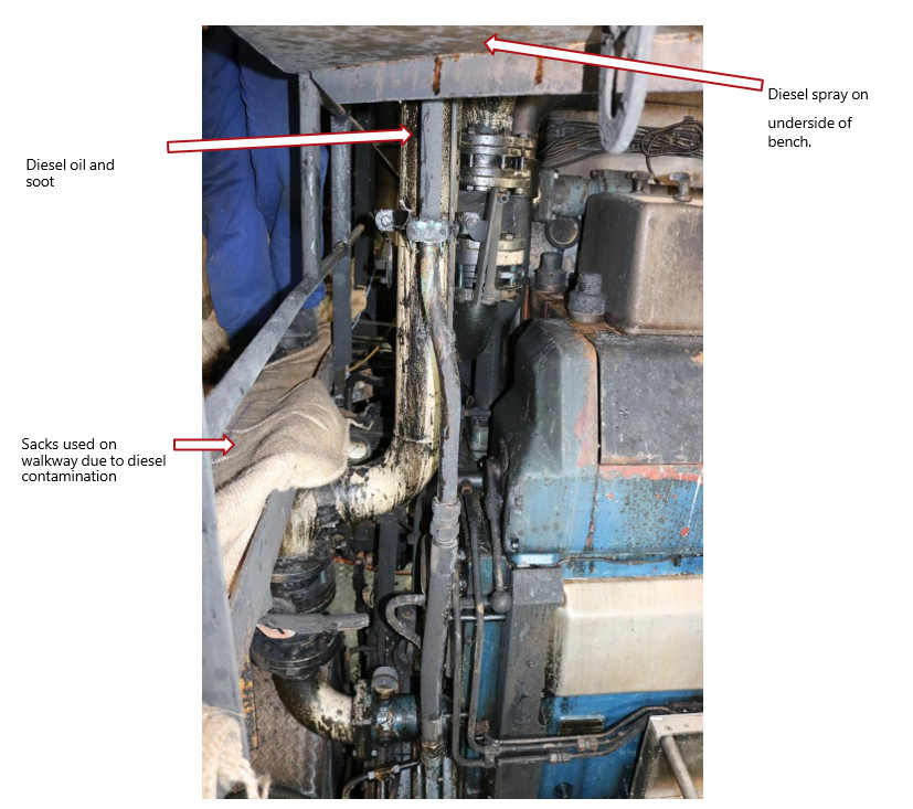
A large Wartsila engine is positioned about the centre of the engine room. Fire damage was evident around one end of the engine with the lowest point of fire damage being in the vicinity of an accumulator connected to the diesel oil supply to the engine. Diesel oil was found above the accumulator and had reached the ceiling of the engine room as well as covering the wall and walkway in front of the engine.
Fire damage had burnt through insulation on wiring, rubber components of pipework and soot deposits were found on steel components.
Statements from the Chief Engineer reported that following the fire the accumulator had been found in the sump below the diesel oil filters.
There were normally two accumulators located around the vicinity of the fuel filters. The accumulators are made from steel and use a diaphragm to dampen pressure fluctuations and therefore ensure a constant diesel oil pressure is provided to the engine. It normally runs at 8bar (800kPa).
One accumulator at the front of the engine was in place and has a bracket to support its weight and prevent inadvertent movement caused by vibrations of the engine. The other accumulator was unsupported with no bracket holding it in place, instead relying on the steel pipework to support it. This accumulator is the one reported to be found in the sump. Post fire the engineers on board have capped the feed to the missing accumulator and it was in this capped condition during my investigation.
Spread of diesel oil and burn patterns from the fire directly above the accumulator support the theory that it had separated from its threaded connection allowing diesel oil to coat the structure and pipework/fittings above this point.

Exhaust gases leave the engine via pipes from each cylinder and then enter a manifold which is surrounded by protective covers to prevent injury due to the heat. The ship’s Chief Engineer stated that these covers typically operate at around 70-80°C.
Between the engine and the manifold, hot exhaust gases are piped through an area known as the manifold box which is capped at each end with a steel cap. The cap can relatively easily be opened and doing so gives direct access to exhaust manifold pipes, clamps etc. The Chief Engineer stated that these pipes typically operate at around 350°C.
The cap at the end of the manifold box was inspected during the investigation and was found to have some rust forming to one side of the cap, however the rest of the cap retained a black coating.
The manifold box end cap was well within the area that had been coated with diesel oil spraying from where the accumulator was located.
Inspection of the accumulator which had detached from its pipeline did not indicate why it had become detached.
Fire damage was found below the flooring next to the engine and this was caused by the fire following the diesel oil flow under that flooring.
Point of Origin
The point of fire origin was identified and confirmed as within the area of the manifold end box.
The accumulator has detached from its pipework and diesel oil spray from the resulting open connection has sprayed onto surfaces above, including the manifold cap. It is most likely that some of this diesel oil has come into direct contact with the hot exhaust manifold, exhaust pipework and/or clamps. A small inspection flap at the forward end of the engine was found unsecured and would have allowed diesel oil to enter the area housing the exhaust manifold.
The ignition temperature of diesel ranges between 233°C and 256°C (Babrauskas, 2003).
Hot surface ignition of the diesel oil has most likely occurred, and the fire has then travelled back along the diesel oil covered engine componentry and/or diesel oil spraying from the accumulator’s open connection.
The engine room alarm has alerted the Chief Engineer and when he arrived in the engine room the flame had travelled all the way back to the open connection feeding the missing accumulator, creating the “geyser of flame” described by the Chief Engineer when he arrived in the engine room.
The cause of this fire is believed to be the hot surface ignition of diesel oil which was spraying from an open pipe where an accumulator has detached from its normal mounting position.
Elimination of Other Possible Causes
Power was on at the time of the fire; however, no evidence of an electrical cause was found. All damage to electrical wiring and equipment appears to be caused by radiant heat damage as a result of the fire.
No evidence of a natural or deliberate ignition source was discovered.
Based on the evidence available at the time, this fire has been recorded as accidental.
References
(Babrauskas, 2003). The Ignition Handbook, Vytenis Babrauskas, Fire Science Publishers 2003, Issaquah WA. Retrieved 3 February 2021
Quest Integrity Metallurgy Report


Related Recommendations
The Commission recommended that Maritime New Zealand ensure that as soon as reasonably practicable the owner of the Amaltal Enterprise install a new system that complies with current maritime rules and put in place additional measures to manage the risk created by the limitations of the current fire-extinguishing system until such time as the new system is installed.
The Commission recommended that Talley’s introduces a system for managing contractors working on board. The system should include sign-off for each task, a job safety analysis for each task that may pose risks to the contractors or crew, and, where applicable, testing to ensure the repaired system is fit for purpose.