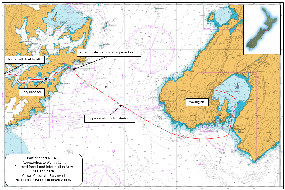
On 5 November 2013 the passenger and freight ferry Aratere was in Cook Strait en-route from Picton to Wellington when the starboard propeller shaft fractured and the propeller was lost. The ship was able to complete the trip using its port propulsion system only. When the ship arrived in Wellington, divers confirmed that the starboard propeller tail shaft had totally fractured within its tapered section, near the forward end of the propeller.
Executive summary Tuhinga whakarāpopoto
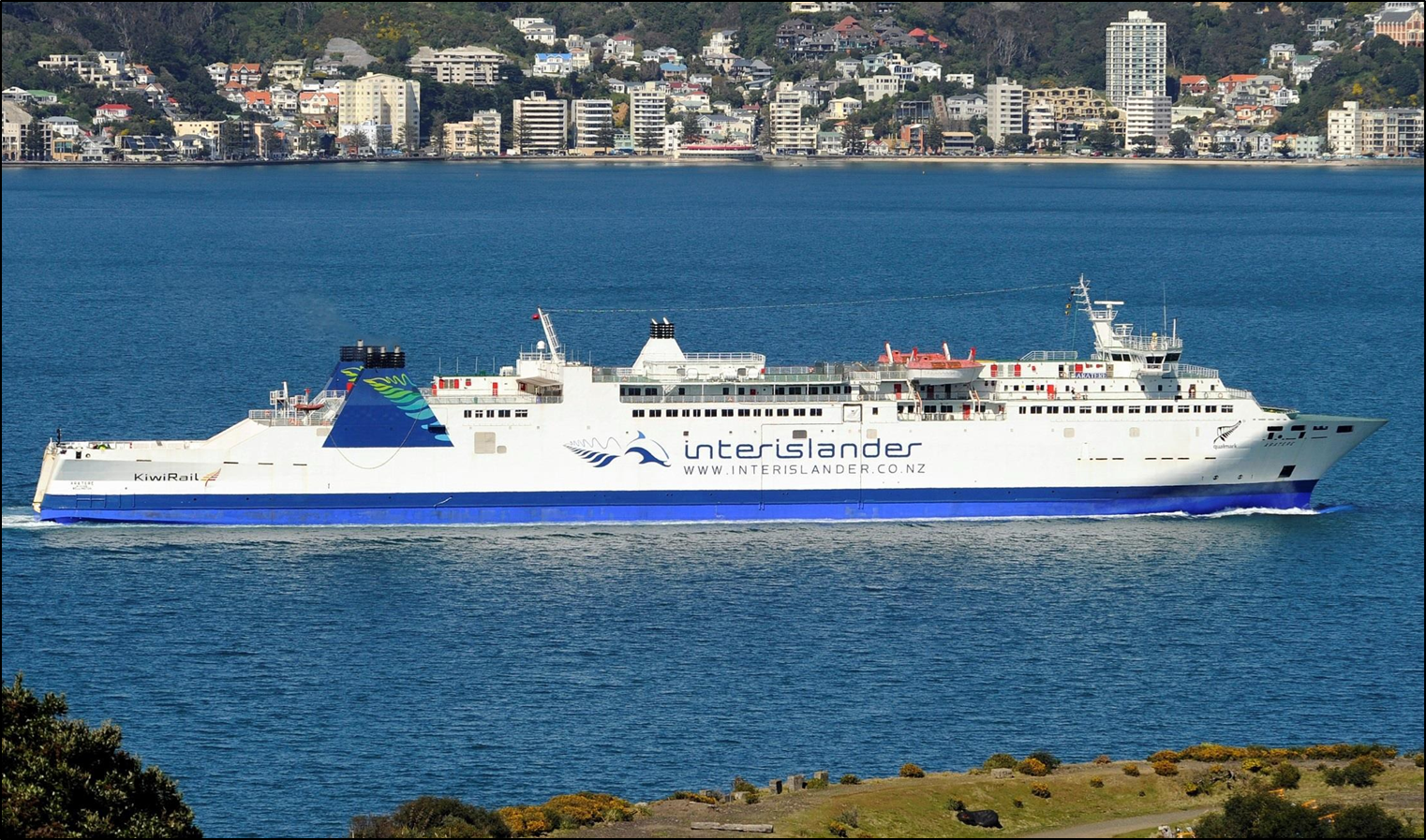
- On 5 November 2013 the passenger and freight ferry Aratere was in Cook Strait en-route from Picton to Wellington when the starboard propeller shaft fractured and the propeller was lost. The ship was able to complete the trip using its port propulsion system only.
- When the ship arrived in Wellington, divers confirmed that the starboard propeller tail shaft had totally fractured within its tapered section, near the forward end of the propeller.
- New propellers had been fitted to the Aratere’s existing propeller shafts as part of a larger project to lengthen the vessel more than two years prior to the incident. The starboard propeller along with the remaining section of the tail shaft was later recovered from the seabed.
- The Transport Accident Investigation Commission (Commission) found that the shaft failed due to a fatigue fracture that had grown (propagated) through the tail shaft to a point where it was unable to carry normal operating loads.
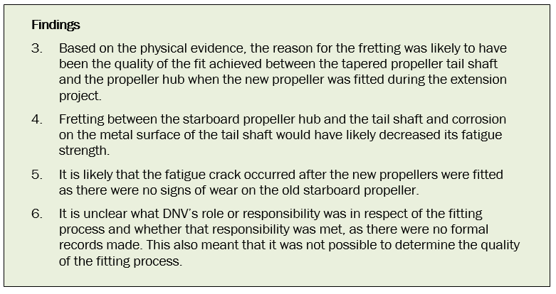
- The fatigue crack initiated in an area of fretting on the shaft taper just inside the bore of the propeller hub. The fretting was likely to have been the result of a sub-optimal fit of the new propeller onto the existing tail shaft. Fretting and corrosion weakened the tail shaft and made it more prone to fatigue failure.
- The Commission found that vibration from a number of potential sources and uneven thrust between the individual blades of the propeller caused sufficient uniaxial bending forces to drive the fatigue crack through the tail shaft. The uneven thrust was the consequence of minor differences in the average pitch of each blade resulting from the manufacturing process, but more so due to the blades being damaged while in service.
- The Commission also found a lack of documentation about the process of fitting the propellers and the final fit achieved. This is significant because the fitting of the starboard propeller resulted in fretting, which weakened the shaft. A recommendation has been made to the Chief Executive of KiwiRail to address this issue.
- The Commission has also made a recommendation to Standards New Zealand to forward the report to the International Organization for Standardization Secretariat for its information and to consider whether the current standards for manufacturing large-diameter marine propellers are appropriate for modern, high-efficiency propellers that operate closer to cavitation margins.
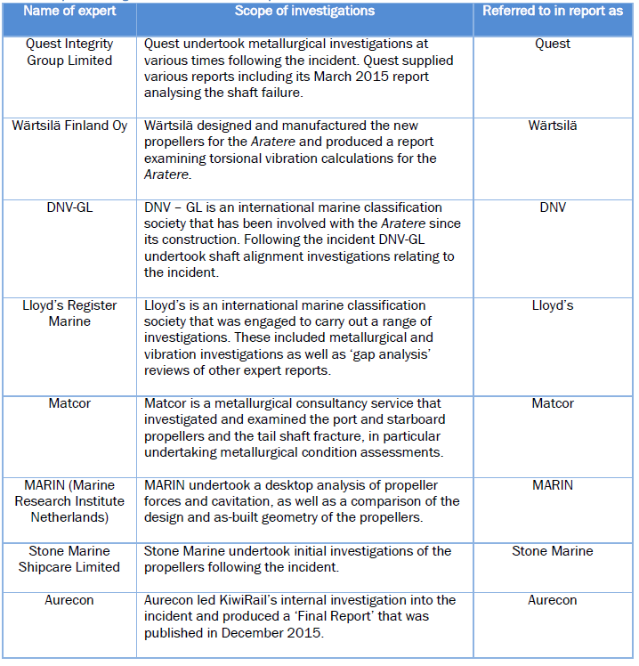
Reference to expert reports
At various times following the incident, KiwiRail engaged multiple experts to undertake testing and analysis. The Commission obtained several of the experts’ reports and its investigators were present at some of the tests the experts undertook. For ease of reading, the table below lists the experts referred to in this report and the investigations they undertook.
Conduct of the inquiry He tikanga rapunga
- On 6 November 2013 at about 0730, the Transport Accident Investigation Commission (Commission) was notified that an incident involving a passenger ferry, the Aratere, had occurred.
- The Commission opened an inquiry into the occurrence under section 13(1)b of the Transport Accident Investigation Commission Act 1990 and appointed an investigator in charge.
- That day two investigators attended the vessel in Wellington, where it was docked. The investigators conducted interviews with the crew of the vessel and collected evidence.
- During the next few days the investigators were involved in liaising with staff at KiwiRail Limited’s ferry operations head office and collecting further evidence, including a download of the voyage data recorder and videos of the underwater inspections of the propeller shafting.
- Further information was sourced from the propeller and power train manufacturer, the vessel’s classification society, metallurgists, Lloyd’s, structural engineers and propeller experts.
- On 23 April 2015 the Commission approved the draft final report to be circulated to interested parties.
- The report was distributed to 10 interested parties with a closing date for receiving submissions of 30 June 2015; on request the closing date was extended to 17 July 2015. Submissions were received from eight interested parties.
- The submissions were substantial and included divergent opinions from several subject-matter experts.
- After receiving submissions, the Commission sent its draft final report to the commercial arm of the Australian Maritime College (AMC Search) for an independent peer review. The Commission received the peer review on 25 November 2015. The peer review recommended that further work be done to resolve some of the divergent views expressed in the submissions. This work was conducted in the ensuing months, and the report was then redrafted to incorporate the submissions received, AMC Search’s comments, and the results of the additional research.
- On 27 July 2016 the Commission, considering the substantial changes made to the report, approved the draft report being sent back to interested persons for further consultation.
- The report was distributed to 11 interested parties with a closing date for receiving submissions of 12 September 2016; on request the closing date was extended to 30 September 2016. Submissions were received from four interested parties.
- The Commission has considered in detail all submissions made and any changes as a result of those submissions have been included in the final report.
- On 2 November 2016 the Commission approved the report for publication.
- On 16 November the Commission received a further submission from KiwiRail in response to the final safety recommendation made to KiwiRail.
- On 24 November the Commission heard from KiwiRail on its submission and any changes as a result of the further submission have been included in the final report.
Factual information Pārongo pono
Narrative
The day of the incident
- At about 1830 on 5 November 2013, the rail, passenger and freight ferry Aratere departed Picton on a scheduled voyage to Wellington. There were 39 crew and 114 passengers on board.
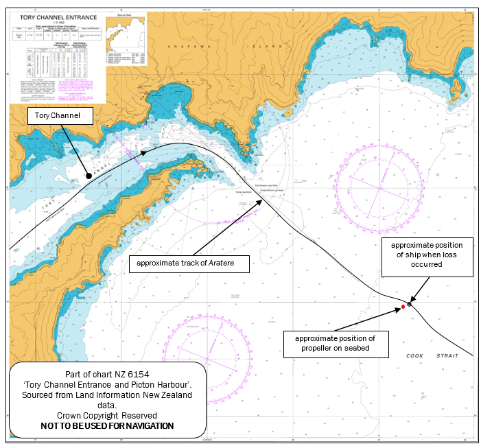
- The Aratere’s passage through the Marlborough Sounds was uneventful and at about 1934 the vessel was passing abeam of East Head at the entrance to Tory Channel (see Figure 1).
- Once clear of the Tory Channel entrance the second mate was handing over the control of the navigation to the third mate when they heard two loud noises that reverberated through the ship.
- The second and third mates checked that they had not hit an object in the water. They then checked the instrumentation on the bridge and noted that no alarms had registered. Everything appeared to be normal except that no load was registering for the starboard propulsion system (that is, the propulsion system was not producing any thrust).
- The third mate telephoned the engineer in the control room, who reported that he knew of no problem and that no alarms had registered. The second mate contacted the duty master, who made his way to the bridge.
- The chief engineer was in his office when he heard the bangs. He checked outside to see if the vessel had hit anything, then returned to his office and checked his engine room monitoring screen. Everything looked normal, so he made his way to the bridge. The chief engineer then telephoned the engine control room and asked the (night) first engineer to check the couplings between the propulsion motors and gearbox, and the propeller shaft couplings.
- The chief engineer then made his way to the engine control room. As he was doing so the master ordered the engines to stop until a further investigation had taken place.
- By the time the chief engineer arrived in the engine control room the first engineer on duty had completed checking the couplings. A low-level alarm had activated for the oil in the starboard stern-tube tank.
- The chief engineer checked the couplings in the engine room. He then entered void-space (an area below deck that contains nothing, and is enclosed by bulkheads with limited openings. A void-space may also be an entirely enclosed space) number eight, where the coupling between the intermediate shafts and the tail shaft was located. While there he asked that power be applied to the starboard shaft to check if it was fully rotating. The shaft rotated normally, but there was no indication of the propeller producing any thrust.
- Meanwhile, the first mate went down to the stern of the vessel, and as the starboard shaft was being tested could see no wash being produced.
- The master and chief engineer concluded that either the starboard propeller had been lost or the shaft was not rotating it. The master decided to continue to Wellington on the port shaft and propeller alone, and advised the passengers of the situation.
- The master and chief engineer then contacted the various maritime authorities and managers to advise them of the situation, and of the possibility that the vessel was leaking oil through the stern shaft seal. Tugs and divers were available on the vessel’s arrival at Wellington.
- After the Aratere had berthed in Wellington, a team of divers inspected the underwater area at the stern of the vessel. They discovered that the starboard shaft had broken aft of the stern-tube seal and that the starboard propeller was missing (refer to Figure 4 on page 9 for a diagram of the parts of the propeller). The divers took high-resolution photographs of the fractured shaft before the shaft end was capped (the damaged end of the shaft was capped to prevent oil escaping from the stern-tube seal and water from entering the stern-tube. The cap helped to protect and preserve the fracture surface for later examination).
Recovery of the propeller and shaft stub
- A specialist company engaged by KiwiRail found the propeller and shaft stub on the seabed on 23 November 2013, and recovered them on 10 December 2013. The propeller was recovered close to where the Aratere’s crew had heard the double bang. (See Figure 2.)
- The propeller was taken to the Commission’s technical facility in Wellington.
Examination of the propeller, the propeller cone and the two surfaces of the fracture
- The propeller, the propeller cone and the stub of the shaft remaining in the hub of the propeller were separated. Representatives from the Commission, KiwiRail, the propeller manufacturer and the classification society were present.
- KiwiRail engaged several experts to assist with its own investigation into why the propeller shaft had fractured. These experts included Quest (a consultant metallurgist), Aurecon (a structural integrity consultant) and Stone Marine (a propeller repair expert). At KiwiRail’s request, Lloyd’s provided a specialist. The Commission participated in various tests undertaken by these experts, which included examinations and measurements of the propeller, propeller cone and various samples from the propeller and tail shaft.
- Aurecon produced a three-dimensional laser surface scan of the propeller. The scan was used to develop a three-dimensional, computer-generated model of the propeller for examination and further testing.
- The stub of the shaft was taken to a metallurgical laboratory, where Quest’s and Lloyd’s experts examined and conducted metallurgical tests on it. The Commission received the reports of these examinations and tests.
- KiwiRail arranged for the Aratere to be dry-docked in Singapore so it could replace the fractured starboard shaft and, if possible, repair the recovered propeller. While the vessel was in dry-dock KiwiRail engaged Matcor, which carried out metallurgical tests and examinations of the section of the fractured starboard tail shaft left protruding from the stern tube of the ship.
- The alignment of both propeller shafts was checked by DNV while the ship was in dry-dock.
Vessel information
Description
- The Aratere is a passenger and freight ferry owned and operated by KiwiRail. When the vessel was built in Spain in 1998, it was designed to comply with the International Convention for the Safety of Life at Sea 1974 as amended, a convention adopted by the International Maritime Organization.
- The Aratere trades on a scheduled service between Wellington and Picton with a service speed of 19.5 knots. It was initially certified to carry a total of 399 persons and was powered by up to four diesel-driven, direct-current generators that provided electrical power as required. This power was supplied via frequency converters to four alternating current electric propulsion motors; two to each shaft. The two electric motors on each shaft either singly or together drive a fixed-pitch propeller through a reduction gearbox.
Vessel lengthening
- In 2010 KiwiRail began a project to lengthen the Aratere to create extra capacity. In April 2011 KiwiRail sent the Aratere to a dry-dock facility in Singapore to have a section approximately 30 metres long inserted into the mid-length of the vessel. Also while in dry-dock: a new modified bow section was fitted; the stern profile was altered; two extra diesel-driven, direct-current generators were fitted; and two new, more efficient propellers were fitted.
Analysis Tātaritanga
Overview of propeller shaft failures
Introduction
- In this section we explain, in general terms, propellers and propulsion systems. We discuss what conditions might cause, or contribute to, a failure of the type seen in the Aratere’s propeller tail shaft.
- The various experts’ reports contain valuable evidence and observations. The inquiry drew on the reports for its own analysis. The reports analysed the fatigue crack and shaft failure, and the possible causes of the failure. Several of the investigations were undertaken immediately following the incident while others, which were more comprehensive, were undertaken at later stages.
Propellers and propulsion systems
Propellers
- The report refers to the parts of propellers, which are defined below. Some are illustrated in Figure 3.
- The hub is the centre of the propeller. Its function is to provide a method of attaching the propeller shaft to the blades.
- The blade root is where the blade is attached to the hub. Typically, this is the thickest part of the blade.
- The blade is the helical formed section of the propeller that transmits the rotational torque of the propeller shaft into thrust to propel the vessel. Blades are designed with all kinds of profile and outline, each offering various benefits in converting torque to thrust. The blade acts like an aerofoil, so the shape and thickness are both critical to the performance of the propeller, particularly with respect to cavitation.
- The blade pressure face is the high-pressure side of the propeller blade facing away from the bow of the vessel, which pushes the water away from the propeller. It is also known as the ‘face’ of the propeller.
- The blade suction face is the low-pressure side of the propeller blade facing towards the bow of the vessel, which sucks the water towards the propeller. It is also known as the ‘back’ of the propeller.
- The leading edge runs along the blade outline from the root to the tip, separating the pressure and suction faces of the blade. A sharp leading edge reduces the load on the shaft but increases the chance of damage. Most leading edge profiles are a trade-off between strength and load.
- The trailing edge runs along the blade outline from the root to the tip; it is where the water exits the blade. The profile of the trailing edge is critical in reducing noise and harmonics.
- The blade tip is formed between the leading and trailing edges on the blade outline. The distance from the centre of the hub to the blade tip multiplied by two describes the propeller diameter.
- The wake is the flow of water in which the propeller acts to propel the vessel forward. The flow of water is influenced by the shape of the underwater hull of the vessel ahead of the propeller.
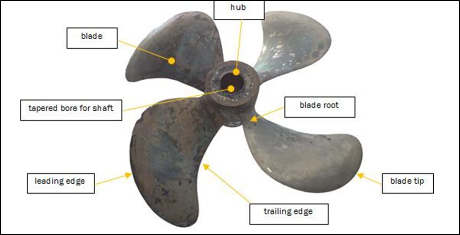
- Propeller manufacturers mark propellers in the vicinity of each blade to differentiate between them. Wärtsilä, the propeller manufacturer, stamped the hubs of the Aratere’s ‘new’ propellers next to the root of each blade A, B, C and D. This report uses the same lettering to describe each blade.
What is a propeller shaft?
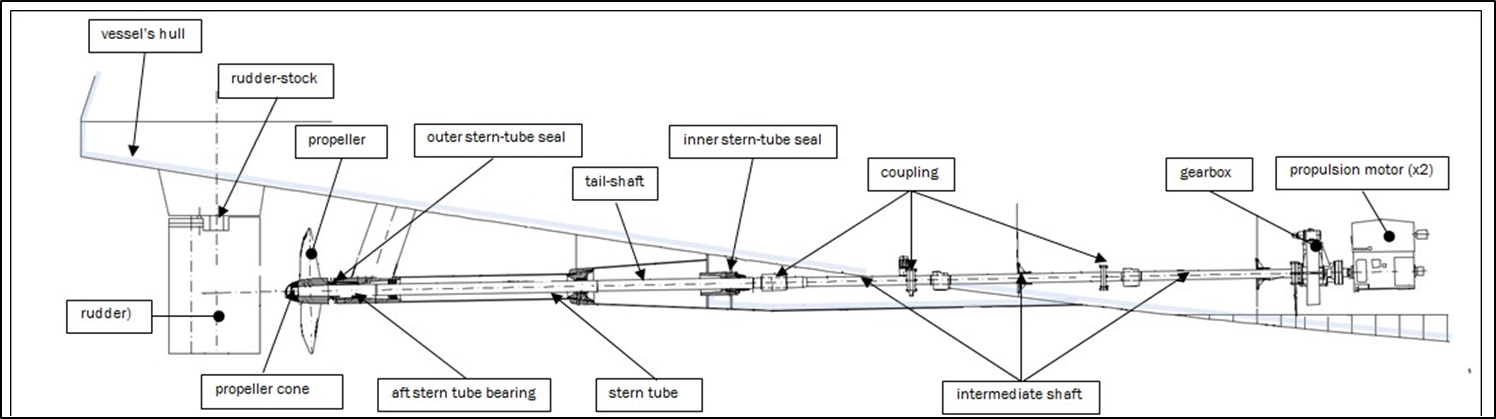
- A propeller shaft usually comprises a tail shaft and several sections of shaft between the tail shaft and the gearbox called intermediate shafts. Where the tail shaft passes through the hull of the vessel it is enclosed by a stern-tube (see Figure 4). On the Aratere the propeller shaft had two main sections made up of (see Figure 4):
- three intermediate shafts, which had a basic diameter of 275 millimetres (mm) and lengths of 4.000 metres, 6.025 metres and 6.000 metres, and
- the tail shaft, which had a basic diameter of 340 mm, increasing to 352 mm where it passed through the aft stern-tube bearing, and was 15.105 metres long.
- A propeller shaft transmits power from the gearbox to the propeller located at the stern of the vessel outside the hull. It also transmits the thrust back from the propeller to the thrust bearing in the gearbox, which is attached to the vessel, and the thrust is what propels the vessel through the water.
- The total weight of the propeller shaft is supported by bearings; these are usually located on pedestals within the engine room, and inside the stern-tube. The bearings in the stern-tube are built in to the stern-tube and the weight of the stern-tube is supported by the after-end arrangements of the vessel’s structure. The bearings are fixed in place to keep the propeller shaft in the correct alignment both vertically and horizontally between the aft stern-tube seal and the gearbox or engine.
- Seals are fitted at either end of the stern-tube to prevent sea water seeping inside the vessel and to stop lubricating oil from the bearings seeping into the sea.
How are propellers fitted to the propeller shaft?
- Propellers are (usually) fitted to propeller shafts by means of an ‘interference fit’. In this method, the fastening between the propeller and the shaft is achieved by friction after the parts are pushed together. The DNV classification society standards for an interference fit are that a minimum of 70% of the propeller bore must ‘mate’ with the propeller shaft during the ’blue fitting‘ process.
- To measure the interference fit, the taper on the shaft is coated with a thin blue grease. The propeller is then pushed onto the shaft. The inside of the propeller bore is examined to measure the percentage contact between the shaft and the propeller. If the fit is less than 70%, the bore of the propeller is hand-scraped to achieve a better fit. This process is repeated until the required standard is achieved. The propeller hub is then expanded using hydraulic pressure and hydraulically pushed up the tapered tail shaft. The hydraulic pressure is released and the propeller hub shrinks onto the tail shaft, thus achieving the ‘interference fit’.
The consequence of a propeller failure
- Many passenger ferries designed and built for short voyage trades (including the Aratere) have duplicate propulsion systems. This redundancy is built in to such vessels to mitigate the risks inherent in their type of operation — they operate in confined or congested waters for a high proportion of voyages and do frequent manoeuvring in and out of berths. If one propeller is lost from a vessel that has two of them, it can continue operating (as illustrated by the incident involving the Aratere, which was able to complete its voyage despite losing a propeller).
- The fracture of a tail shaft on a modern vessel is, however, unusual. A high percentage of the world’s shipping fleet is fitted with only a single propulsion system. For example, in 2011 almost all of the approximately 3,600 large tankers in the world were propelled by single propellers.
- For this reason, lessons from this incident have implications for the world shipping fleet.
Causes of propeller shaft failure
- There are four basic mechanisms that can cause a shaft to fail: corrosion, wear, overload and fatigue. The first two, corrosion and wear, very rarely cause shaft failures in and of themselves, and when they do they leave clear evidence. Of the other two mechanisms, fatigue is more common than overload failure. Whilst corrosion and wear are rarely the sole cause of shaft failure, corrosion and/or wear will often act in conjunction with fatigue loading to cause a shaft failure (Sachs, 2012). In this case there was no evidence of failure due to wear or purely overload; instead the evidence suggested that shaft failure as a result of fatigue was likely. Accordingly, fatigue cracking was one of the main areas of interest in the Commission’s investigation.
- A complete fatigue fracture of a propeller shaft requires two things to have occurred:
- the formation of a fatigue crack
- the propagation of the fatigue crack through the propeller shaft, resulting in complete failure.
- To understand what conditions allow a crack to form then propagate, it is useful first to understand fatigue and the related subject of stress.
Metal fatigue and stress
-
In engineering, metal fatigue has been defined as the (Pook, 2007):
gradual degradation and eventual failure that occur under loads which vary with time, and which are lower than the static strength of the metallic specimen, component or structure concerned. The static strength is the load which causes failure in one application. The loads responsible are called fatigue loads. These loads are cyclic in nature, but the cycles are not necessarily all of the same size or clearly discernible. A fatigue load in which individual cycles can be distinguished is sometimes called a cyclic load.
- Fatigue begins when the surface of the metal deforms because of mechanical damage, allowing a crack to develop. An example of mechanical damage that can occur on a propeller shaft is minute hammering of the tail shaft surface caused by fretting between the propeller hub and the propeller shaft. Surface defects such as manufacturing defects or corrosion pits can be a mechanism for the crack initiation. Cracks work their way into the metal from these surface deformations. As cracks develop, the metal tears. If undetected, a crack may eventually cause catastrophic failure.
- A certain level of stress (stress is a physical quantity that expresses the internal forces that neighbouring particles of a continuous material exert on each other. Stress inside a material may arise by various mechanisms, such as reaction to external forces applied to the bulk material (like gravity) or to its surface (like contact forces, external pressure, or friction) (Lubliner, 2008) [as above re definition of different types of stress]) is required to cause fatigue. A rotating propeller shaft is subject to several stresses, which can result from the action of many different forces. However, not all these forces necessarily act simultaneously or on the same areas of the shaft. In addition, the level of stress resulting in fatigue is lower if any of the following factors alter the surface condition of the metal (Quest Integrity Group (2015). ‘Aratere’ Starboard Propeller Shaft Failure Investigation, section 4.1):
- stress concentration
- manufacturing or materials issue
- local stress, including residual stress and contacting stresses
- fretting and corrosion.
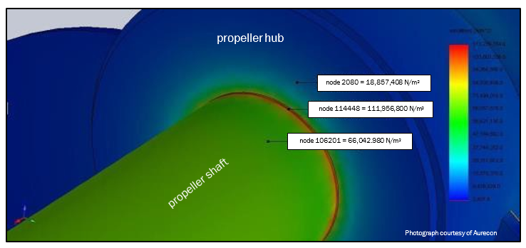
Stress concentration
- Some of the stresses on a propeller shaft are unavoidable due to the method of construction. An example is the clamping stress of the propeller onto the shaft itself, which is a form of stress concentration. In Figure 5 the red represents a higher level of stress concentration where the front end of the propeller boss clamps onto the propeller shaft. Unavoidable stresses exist in most propeller and shaft assemblies but would normally be well below the crack initiation limit (the minimum stress required to initiate a fatigue crack in a substance). A propeller shaft is designed to withstand these foreseen stresses.
Manufacturing or material issue
- It is possible that a manufacturing or material issue exists that causes or contributes to a fatigue failure. For example, if there is a problem with the milling process of the steel it may reduce the expected hardness of the shaft and its ability to resist fatigue stresses.
Local stresses
- Residual stresses can remain in a structure post manufacturing. For example, the heating and cooling of steel as a result of welding can cause the resulting structure to have residual stresses in its resting state.
Fretting and corrosion reduce the amount of stress required to cause fatigue
- Fretting is “a special wear process that occurs at the contact area between two materials under load and subject to minute relative motion by vibration or some other force” (ASM International, 1996). Fretting can occur as a result of a poor fit between the propeller hub and the propeller shaft, resulting in unexpected movement and degradation of the contacting surfaces. “Fretting decreases the fatigue strength of materials operating under cyclic stress. The reduced fatigue strength can result in fatigue cracks initiating in the fretting zone” (Lipsom & Colwell, 1961). Afterwards, the crack can propagate into the shaft if sufficient forces exist to allow this.
- Most metals are vulnerable to corrosion and this is especially so when metals are potentially in contact with salt water. Like fretting, corrosion alters the surface of metals, making them more susceptible to fatigue cracking.
- Alone or in combination, fretting and corrosion can reduce the fatigue limit to as low as one-tenth that in dry air, and therefore make a propeller shaft more vulnerable to fatigue (Quest Integrity Group (2015). Aratere Starboard Propeller Shaft Failure Investigation, section 4.1).
Vibration
- If fretting or some other cause has initiated a fatigue crack in a propeller shaft, bending in the shaft can result in the crack growing. Vibration is one of several bending stressors that can emanate from different parts of the propulsion system and for different reasons. External sources can also induce vibration in the propulsion system.
- Vibration can be lateral or torsional. Lateral vibration is movement orthogonal to (that is, at right angles to) the shaft’s axis. Torsional vibration is twisting about the shaft’s longitudinal axis. Measurements of both are used to identify potential problems within the propulsion plant and determine the fatigue life of an individual part or assembly within the propulsion system. The two types of vibration can be analysed separately or together. Frequently one causes the other. For example, lateral vibration in the tail of an aircraft produces torsional vibration in the fuselage, and the firing of pistons in a large marine engine can cause twisting forces in the propeller shaft.
- All systems, including propulsion systems, have a natural level of vibration. Resonance occurs when the natural vibration is multiplied by vibration from another source that is at the same frequency as the natural vibration of the system.
Alignment of the propeller shaft
- If the entire propeller shaft is incorrectly aligned, the load on the motors increases and the bearings are subjected to increased stresses. The abnormal stress can result in bearing damage, including breakage and increased vibration.
Cavitation
-
Cavitation occurs when bubbles generated by propellers collapse (implode) and create an intense shock wave, which are strong enough to cause damage to moving parts. Repeated implosions near a metal surface cause cyclic stress. More specifically, cavitation occurs (Kinnas & Young, 2003):
when pressure drops below the saturated vapour pressure of the liquid, consequently resulting in the formation of gas filled or gas and vapour filled bubbles. A type of cavitation that is common on marine propellers is sheet cavitation. It is characterized by a “continuous” liquid/vapour interface which is “attached” to the blade surface. Despite its undesirable nature, some sheet (or other types of) cavitation often has to be accepted in order to maintain efficiency. Thus, accurate prediction of cavitation is very crucial in the design and analysis of marine propellers.
The fracture in the Aratere’s propeller shaft
What type of fracture occurred on the Aratere?
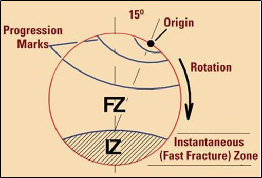
- Various experts (Matcor (2014). Failure Analysis and Condition Assessment of Starboard and Port Propeller Shafts of Vessel ‘MV ARATERE’, section 4.3. Lloyd’s Register (2014). Metallurgical Investigation, section 2.2. Quest Integrity Group (2015). Aratere Starboard Propeller Shaft Failure Investigation, section 4.1) concluded that the type of fracture that occurred on the Aratere’s starboard propeller shaft was a fatigue fracture, typical of that resulting from uniaxial bending forces acting on a rotating shaft. Shaft failures resulting from bending fatigue display a unique fracture surface not seen in other types of shaft fatigue failure. Figure 6 is a drawing of a typical plane bending fatigue failure in a rotating shaft. The drawing shows how a crack starts at the origin and slowly propagates (grows) across the fatigue zone. When the crack reaches the boundary of the instantaneous zone, its growth rate increases significantly. (Sachs, 2012)
- The drawing in Figure 6 shows remarkable similarities to the photograph of the shaft fracture face of the Aratere’s propeller shaft, shown in Figure 7.
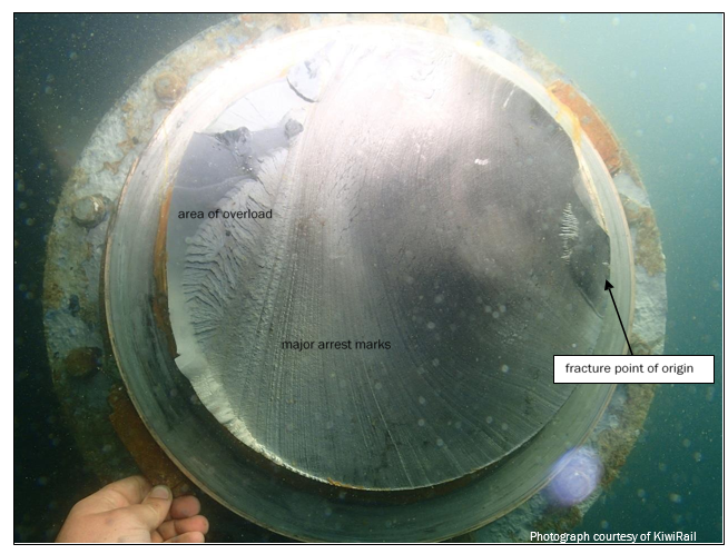
- The Commission determined that the fracture was a fatigue fracture typical of that resulting from bending forces being applied. Figure 7 demonstrates that the fracture seen on the Aratere’s starboard propeller shaft had all the hallmarks of a bending fatigue failure, with readily identifiable fracture origin and progression/arrest marks, and an instantaneous/overload fracture zone.
- Quest described the fatigue crack in the starboard propeller shaft of the Aratere as being multi-origined, indicating that the surface cyclic loading on the shaft was well above the fatigue limit for the material. The amount of stress required to cause a fatigue failure varies depending on the level of average stress present. Quest further concluded that as the crack propagated, the stress concentration increased and the crack grew faster. It was probable that towards the end of the fracture the major arrest marks related to significant changes in the operation of the vessel. These could have been individual sailings or specific loadings where high stress was applied (Quest Integrity Group (2015). Aratere Starboard Propeller Shaft Failure Investigation, section 4.1).
- Other evidence also supports fatigue fracture as a result of bending forces.
- The fracture plane was (aside from the area of final overload) at 90 degrees to the longitudinal axis of the propeller and had a relatively smooth face (Lloyd’s Register (2014). Metallurgical Investigation, section 2.1)
- Progression (beach) marks were present, which was indicative of fatigue crack propagation (Matcor (2014). Failure Analysis and Condition Assessment of Starboard and Port Propeller Shafts of Vessel ‘MV ARATERE’, section 4.3).
- The orientation of the crack suggested the involvement of bending and possible axial stresses (Ibid., section 6.0).
- The presence of other fatigue cracks in the vicinity of the fracture, including an additional fatigue crack that was diametrically opposite the initiation point of the fracture, was indicative of reverse bending forces (Lloyd’s Register (2014). Metallurgical Investigation, section 2.2. Quest Integrity Group (2015) Aratere Starboard Propeller Shaft Failure Investigation, section 3.3).
- The following analysis sections of this report discuss and analyse the possible factors contributing to the fracture.
- The first section (section 6) examines the factors that might have weakened the Aratere’s tail shaft to make it more susceptible to a crack initiating from the forces acting on the tail shaft. The Commission found evidence of fretting and corrosion.
- Section 7 discusses the fitting of the propellers and whether it was a cause of the fretting and corrosion.
- Section 8 examines what factors might have existed that contributed to the crack initiating and then growing once it had been initiated, in particular vibration.
- Section 9 examines the stress loading on the tail shaft as a result of differences in the pitch of each of the propeller blades. The section discusses whether the design and/or manufacture of the propellers contributed to the fracture.
- Section 10 considers the current standards for manufacturing tolerances with respect to marine propellers.
- Section 11 considers cracks in the Aratere’s starboard rudder stock, and oversight of the fitting of the new propellers.
- Section 12 is a summary of the analysis.
Weakening of the tail shaft and initiation of the crack
Introduction
- In this part of the analysis we discuss what factors might have contributed to the weakening of the Aratere’s tail shaft and led to the initiation of a crack.
Was there a manufacturing fault in the tail shaft?
- Advice from Quest, and data provided by Wärtsilä, indicated that a tail shaft manufacturing defect did not contribute to the failure.
- Quest considered the strength of the shaft to be in accordance with the reported strength in the mill certificate. Quest measured the ‘hardness’ of the shaft and the results showed a hardness equating to a tensile strength of 640-840 megapascals (MPa) (the ‘hardness’ test was conducted using the Vickers Pyramid Number (HV). The result was 200-250 HV, which equates to a tensile strength of 640-840 MPa). The steel mill that manufactured the shaft produced a mill certificate indicating an allowable range of 600-650 MPa. The mill certificate for the shaft recorded test results for the shaft of between 650 and 682 MPa.
- Quest’s conclusion, supported by the fact that the propeller shafts had been operating successfully for some 13 years before being fitted with new propellers, ruled out the possibility of a tail shaft manufacturing defect contributing to the failure.
- A propeller shaft is designed to withstand variable stresses. These foreseen stresses include those that occur at the nodes where the end of the propeller hub is clamped to the shaft. Wärtsilä (the propeller designer) provided data that the stresses at the nodes were expected to be double those in the surrounding area. Testing (the engineering firm conducting the tests used a finite element analysis, which is a computational tool that includes the use of mesh generation techniques for dividing a complex problem into small elements, as well as the use of a software program coded with FEM algorithm) following the incident calculated the stresses to be as expected. This further supported the conclusion that there was no manufacturing fault in the tail shaft.
Did fretting and/or corrosion contribute to weakening of the propeller shaft?
Evidence of fretting on the starboard tail shaft
-
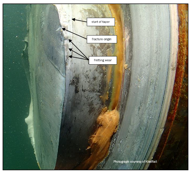
The Aurecon ‘Final Report’ commissioned by KiwiRail concluded that there was no evidence of fretting damage in the origin area of the fatigue crack, and that fretting was unlikely to have been the primary root cause of the failure (Aurecon Final Report at 1, page 1). However, there was evidence of fretting on the starboard tail shaft around the point of origin of the fatigue crack. Figure 8 shows areas of fretting around the circumference of the shaft next to the fracture zone. Quest considered (Quest (2014). Aratere Starboard Propeller Shaft Failure Investigation, section 4.1):
This indicates that one or more of the factors to reduce the fatigue limit were significant. No significant [more than 5 %] corrosion or surface defects were observed on the shaft prior to the failure. However, a significant amount of fretting was present. It is probable that this was a major factor in reducing the fatigue limit. However, where the fretting had occurred between the bronze and steel, the majority of physical damage has occurred to the softer bronze material [of the propeller]. This was seen as fretting pitting, fretting debris and bonding of the bronze material onto the shaft. However, in the steel shaft, even though there was only minor physical evidence of fretting damage, it will have seen a significant surface hammering loading which will have modified the local surface loading. Some evidence was present that this loading was in excess of the yield stress in the material and localised deformation occurred.
- A subsequent report carried out by Quest concluded:
- that the most severe fretting damage was adjacent to blade C (Quest (2015). Aratere Starboard Propeller Shaft Failure Investigation, section 3.2)
- the presence of significant corrosion pitting (Ibid. section 3.3).
- that a significant amount of fretting was present and it was probably a major factor in reducing the fatigue limit (Ibid. section 4.1)
- The Commission’s view, based on its analysis, is that fretting likely reduced the amount of stress required to initiate fatigue failure. The movement of the shaft due to the formation of the fracture would have also caused a certain amount of the fretting; that is, as the fracture propagated through the shaft, movement between the fracture surfaces increased the fretting between the shaft and the propeller hub.
- This view is also supported by the peer review undertaken by AMC Search, which concluded that “on the basis of the evidence it appears safe to conclude that fretting damage occurred and is likely to have caused a stress riser that ultimately led to fatigue” (AMC Search (2015). Peer Review of Report into Marine Inquiry MO-2013-203, at 1.8).
- In addition to the Quest findings in respect of corrosion, Lloyd’s found evidence of corrosion on the starboard propeller shaft around its circumference within 100 mm of the top/forward end of the taper. Lloyd’s determined that the most likely cause of the corrosion was historical sea water contamination of the stern-tube lubricating oil (Lloyd’s (2015). KiwiRail Holdings Ltd: Starboard Propeller Shaft Failure: Gap Analysis, section 7.1).
Comparison with fretting and corrosion in the port tail shaft
-
Evidence of fretting and evidence of corrosion were apparent on the port tail shaft as well as the starboard tail shaft. When the Aratere was dry-docked in 2014, KiwiRail engaged Matcor to assist in its investigation of the incident. Matcor is an expert in the field of materials and corrosion. Matcor’s report on the condition of the port shaft included the following (Matcor Technology & Services Pte Limited (2014). Failure Analysis and Condition Assessment of Starboard and Port Propeller Shafts of Vessel ‘MV ARATERE’, p.1):
The surface of the shaft at the propeller seat hub area was generally satisfactory apart from the scattered presence of irregular blackish patches and copperish tint particularly near the forward end of the hub. Localized corrosion in the form of clusters of minute pits of up to about 1.0mm deep was observed within the irregular blackish areas. The copperish tint observed at scattered areas of the shaft was essentially associated with the aluminium bronze material of the propeller hub that had smeared onto the shaft surface. The microstructure and hardness condition of the shaft was generally satisfactory and consistent with the material specification requirements.
- Both the port and starboard propeller shafts were corroding to some degree and there had been fretting between both propeller hubs and their respective propeller shafts, yet only the starboard propeller shaft failed. This means that either the starboard propeller shaft had been weakened more than the port shaft, or the starboard shaft was prone to more severe vibration than the port shaft, or a combination of the two.
Fitting of the new propellers
Introduction
- In the previous section we presented evidence of fretting between the propeller tail shafts and the hubs of the propellers. As explained in paragraph 4.5.2, fretting between the propeller tail shafts and the hubs of the propellers causes minute hammering of the tail shaft surface. This hammering can cause mechanical damage on the metal surfaces, causing them to deform and allowing a crack to initiate.
- The fretting indicated that the fit between the shafts and the hubs was not optimum. It was therefore necessary to review the fitment of the new propellers in 2011, and whether the fit achieved had been satisfactory. This fitting of the propellers is discussed further in this section.
Replacement of the propellers
- The fitting of the new propellers to the Aratere was part of the project to lengthen the vessel. KiwiRail instructed the shipyard undertaking the lengthening to also fit the new propellers. Replacement of propellers is a significant undertaking, and Wärtsilä advised KiwiRail that the preferred method for fitting the new propellers was to remove the propeller shafts and fit the propellers vertically. An alternative and less desirable method for fitting the propellers is horizontally, which does not require the removal of the propeller shafts. It is a less desirable method because it is technically more difficult and entails a higher risk of damage to the propeller hub or shaft.
- Notwithstanding Wärtsilä’s recommendation, KiwiRail opted for the latter method, which meant the propeller shafts did not need to be removed.
DNV rules for fitting propellers
- When new propellers were fitted to the Aratere in 2011, they should have met standards set by the classification society, DNV.
-
A classification society sets technical standards for the construction and operation of ships. The International Association of Classification Societies describes the aim of ship classification being to (IACS, 2016):
verify the structural strength and integrity of essential parts of the ship’s hull and its appendages, and the reliability and function of the propulsion and steering systems, power generation and those other features and auxiliary systems which have been built into the ship in order to maintain essential services on board. Classification Societies aim to achieve this objective through the development and application of their own Rules and by verifying compliance with international and/or national statutory regulations on behalf of flag Administrations.
- A classification society may issue a certificate of classification for a vessel designed and built to its rules. The certificate does not imply a warrant of safety, fitness for purpose or seaworthiness, because the classification society has no control over how the ship is operated or maintained.
-
The DNV standard for fitting propellers is that at least 70% of the propeller bore must ‘mate’ with the propeller shaft, which is determined through the blue-fitting process. The DNV classification society rules state (DNV, 2013):
Prior to final pull-up, the contact area between the mating surfaces shall be not less than 70% of the theoretical contact area (100%). Non-contact bands (except oil grooves) extending circumferentially around the hub or over the full length of the hub are not acceptable. At the big end there shall be a full contact band of at least 20% of the taper length.
- DNV had changed the rules in 2006 to clarify the final requirement; that is, that at the big end there was to be a full contact band of at least 20%.
- In addition to shipyard and KiwiRail staff, KiwiRail requested a representative of DNV to observe the replacement of the propellers. As part of its investigations the Commission sought information relating to the fitting of the new propellers. None of KiwiRail, DNV or the shipyard was able to provide any reports or notes from the propeller-fitting process.
- KiwiRail’s engagement of DNV to be present at the fitting suggests that KiwiRail expected the DNV representative to check or inspect the fit. A job sheet provided to the Commission stated that the DNV representative was performing an ‘inspection’, which suggests that that person was more than an observer.
- In its submission on the draft report, KiwiRail stated that it had engaged the DNV surveyor to witness and sign off that the fitting of the propeller was done in accordance with DNV rules. KiwiRail stated that it was not appropriate for it to specify what DNV should do or look at while present, and therefore KiwiRail did not expect to have to do so. However, in the Commission’s view, as KiwiRail undertook to complete the fitting of the starboard propeller onto the shaft using its own expert and labour, the responsibility for ensuring that this task was completed satisfactorily rested with KiwiRail. Therefore, it would have been good practice for KiwiRail to have ensured by seeking a report or confirmation from the DNV representative that the fitting process was in accordance with the DNV Rules.
The quality of the fit achieved
- According to KiwiRail staff, the initial fit of the ‘new’ propellers onto the shaft taper achieved only 40% contact with the mating surfaces. Reportedly the majority of the ‘fit’ was at the narrower end of the taper (whereas the DNV rule required the better fit to be at the wider end of the taper). Several attempts were made to achieve an adequate fit. The repeated attempts would have increased the opportunity for damage to occur to the contact surfaces.
- None of KiwiRail, the shipyard or DNV could provide the Commission with any records to show whether the relevant DNV standards were met regarding the level of ‘fit’ achieved between the propeller bore and the tail shaft (DNV was able to supply four photographs of the propeller blueing process, but the photographs were not annotated as to which propeller they depicted or at what stage of the blueing they had been taken). Any fitting achieving less than 100% contact risked fretting from microscopic movements between the tail shaft and the propeller bore, which could have weakened the metal surface and made it more susceptible to fatigue cracking. The distribution of the contact area would have affected how much movement could occur under operational loading. In addition, it is not known whether the repeated fitting attempts caused any damage to the tail shaft or propeller hub.
- The Commission notes that the DNV rules required a full contact area of at least 20% of the taper length at the big end of the hub. This is the area where fretting was observed around the Aratere’s fractured tail shaft (see Figure 9 on page 23).
Longitudinal fit
- When the propeller was fitted onto the tail shaft in dry-dock it should have pushed right up to the end of the taper, where the propeller hub would mate with a mechanical seal on the end of the stern-tube. However, it fell about 8 mm short. Instead of adjusting the bore of the propeller hub, the propeller was withdrawn and an 8 mm spacer was inserted to achieve the required mating between the propeller hub and the mechanical seal (see Figure 9).

- It is not clear whether the 8 mm spacer was required as a result of an overall error in the size of the taper in the propeller hub, or because of high spots and imperfections in the bore created during the propeller manufacturing process. Given that only a 40% interference fit was achieved on the first attempt to mate the propeller hub with the tail shaft, the latter was more likely to have been the case. If this was the case, a substantial amount of ‘linishing’ (an engineering term that refers to the process of using grinding or belt-sanding techniques to improve the flatness of a surface. The flatness may be two-dimensional, i.e. with a view to achieving a flat plate, or one-dimensional, e.g. with a view to achieving a perfectly cylindrical shape) would have been required to achieve the minimum 70% interference fit. Interviews with KiwiRail staff who were assisting with the fitting procedure revealed that this process of blueing, fitting, removing and linishing of the propeller bore was repeated several times in an attempt to get the required interference fit.
Crack testing on the tail shafts
- KiwiRail did not provide the Commission with any records of whether crack tests on the tail shafts had been specified or performed before the fitting of the new propellers. Best engineering practice would have been for KiwiRail to undertake crack testing of the tail shafts to ensure that no cracks were present before the fitting of the new propellers.
- Some evidence suggests that a test was performed (an email between KiwiRail and the propeller manufacturer on 15/02/2011 noted that crack testing had been budgeted for during dry-dock, and the shafting expert engaged by KiwiRail thought he remembered a person carrying out a crack test but could not recall the outcome). Further, experts engaged by KiwiRail considered that the fatigue cracks occurred after the new propellers were fitted, given that there were no signs of wear on the old starboard propeller that corresponded with the wear on the tail shaft.
- Because the Commission was unable to obtain documentation confirming whether crack testing had been carried out when the new propellers were fitted, it cannot be certain about when the crack occurred, but considers the cracking was likely to have occurred after the fitting of the new propellers (see section 5 where this is discussed)
Lack of records and formal oversight of the propeller fitting process
- In the Commission’s view it is significant that KiwiRail, and to a lesser extent DNV or the shipyard, could not provide any records from the propeller-fitting process to the Commission. It suggests that KiwiRail had no way of knowing whether the propellers had been fitted correctly and whether the relevant rules had been met.
- The replacement of propellers on a vessel the size of the Aratere is a significant undertaking and it would be normal for formal records of the process to be available. There is no evidence of KiwiRail following up with DNV about its representative’s inspection or observations of the fitting process, or whether KiwiRail sought a report of that person’s inspection.
Crack propagation from vibration
Introduction
- In section 5 we presented evidence showing that it was a fatigue fracture that occurred on the Aratere’s starboard propeller. As the fatigue fracture propagated as a result of uniaxial bending, it is necessary to determine what sources of uniaxial bending existed. The main sources of uniaxial bending are vibration and abnormal uneven thrust between individual blades of the propeller.
- External sources of vibration can induce vibration in a propulsion system, but this was unlikely for the Aratere because no vibration from external sources was noted on the vessel before the incident. Therefore, this section examines potential sources of vibration from within the Aratere’s propulsion system to determine if vibration was a factor.
Did resonance contribute to the tail shaft failure?
-
In physics, elasticity is the ability of a body to resist a distorting influence and return to its original shape when the distorting influence (stress) is removed. In this case the Aratere’s propeller shaft and propeller was an elastic body. As explained by Bhatt (2010):
any elastic body can vibrate freely. Its vibrations are called natural vibrations. Frequency of these vibrations is called natural frequency. Each vibrating body has its natural frequency. (Bhatt, 2010)
- Resonance is when a vibrating system or external force drives another system to oscillate with a greater amplitude at a specific frequency. The resonant frequency is approximately equal to the natural frequency.
- For the Aratere’s propeller shaft and propeller, there is a critical speed of rotation or blade pass frequency that excites the natural frequency of the propeller shaft or propeller. As this speed of rotation approaches the propeller shaft and propeller’s natural frequency, the propeller shaft and propeller begins to resonate, which dramatically increases the propeller shaft and propeller’s vibration.
- Following the incident, Wärtsilä and Lloyd’s produced calculations that indicated resonance was unlikely to have contributed to the tail shaft failure. These calculations are discussed next.
Lloyd’s calculations of vibration
- Lloyd’s carried out calculations of the natural frequencies of shaft-line lateral vibration for the Aratere in December 2013, after the incident. It found that the frequency of natural vibration of the shaft (where it would vibrate freely without any extra external force applied) was within the normal operating revolutions of the propeller and shaft. Thus any forced vibration induced into the system at the frequency of natural vibration, for whatever reason, would have caused a manifold increase in the amplitude of the natural vibration (resonance).
Wärtsilä’s calculation of vibration
- In 2010 Wärtsilä designed a modification to the propeller cones (refer to the section on propeller weight and balance below). At the time Wärtsilä recommended to KiwiRail that it calculate torsion and vibration. In correspondence with Wärtsilä KiwiRail advised that it had asked a shafting expert to carry out the torsional and vibration calculations. KiwiRail was unable to produce the calculations, so it is unknown whether they were ever completed.
- Following the incident Wärtsilä completed torsional and vibration calculations. The calculations showed torsion and vibration were within acceptable limits, and therefore unlikely to have contributed to the tail shaft failure.
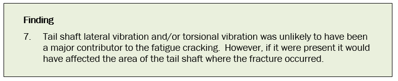
- Cyclic stress would have elevated lateral vibration in the part of the shaft between the face of the propeller hub facing forwards and the aft stern-tube bearing, in close proximity to where the fracture did occur. If lateral vibration had been present, it would have manifested in the place the crack initiated. Lloyd’s report indicated that lateral vibration could not be excluded as a possible contributing factor to the formation of the fracture in the shaft.
-
Lloyd’s report stated (Lloyd’s (2014). Interislander: Calculation of Natural Frequencies of Shaftline Lateral Vibration, section 6.1-6.2)
It is likely that the shaft-line first natural frequency of lateral vibration has been within the range of blade rate (blade rate excitation is the rotational frequency of the shaft (revolutions) multiplied by the number of blades on the propeller) excitation generated during normal vessel operations. The history of problems with the port and starboard aft stern seals and associated water contamination of the stern-tube lubricating oil are also generally symptomatic of lateral vibration.
Resonance at the first natural frequency of lateral vibration would result in elevated levels of cyclic bending stress in the shaft forward of the propeller and in way of the ‘A’-bracket bearing. Vibratory amplitudes would be controlled by damping around the propeller and oil film damping in the ‘A’-bracket and auxiliary bearings.
- Therefore, it is possible that lateral vibration contributed to the failure of the Aratere’s starboard propeller shaft. Although lateral vibration would have made only a minor contribution to the failure, it would nevertheless have added to any accumulation of other factors.
Did misalignment of the propeller shaft contribute to the shaft failure?
The consequences of a misaligned shaft
- A misaligned propeller shaft increases vibration above that for a well aligned shaft. Increased vibration is likely to contribute to the bending forces that, if sufficient, initiate and propagate a fatigue crack.
- Misalignment also increases the load on the propulsion motors and generators, because more power is required to rotate the shaft. There would also be an increased load on the bearings, which could lead to premature wear and possible breakage.
History of the alignment of the Aratere’s propeller shafts
- Since being built in 1998 the Aratere had had several problems with the alignment of both its port and starboard propeller shafts, resulting in realignments on three occasions between 2003 and 2013. These issues are described in more detail in Appendix 1; however, the Commission notes that the aft stern-tube bearing had fatigue-type damage, and the starboard aft stern-tube bearing had a large piece broken off that was likely to be from fatigue (Lloyd’s (2015). KiwiRail Holdings Ltd: Starboard Propeller Shaft Failure: Gap Analysis, section 6.2).
- When the Aratere was in dry-dock in Singapore in 2011 to lengthen the vessel, a KiwiRail contractor advised on, and dealt with, aligning and fitting the propeller shafts and new propellers.
- The contractor took measurements before and after the hull was extended, which showed there was a 25 mm shift to port and 10 mm downward roll of the hull. The contractor also supervised the realignment of the port and starboard shafts once the vessel was afloat. It did this while the tail shafts were in place (that is, it did not remove them from the hull, which would have been the preferred practice because it would have allowed the propeller shafts to be aligned along their whole length).
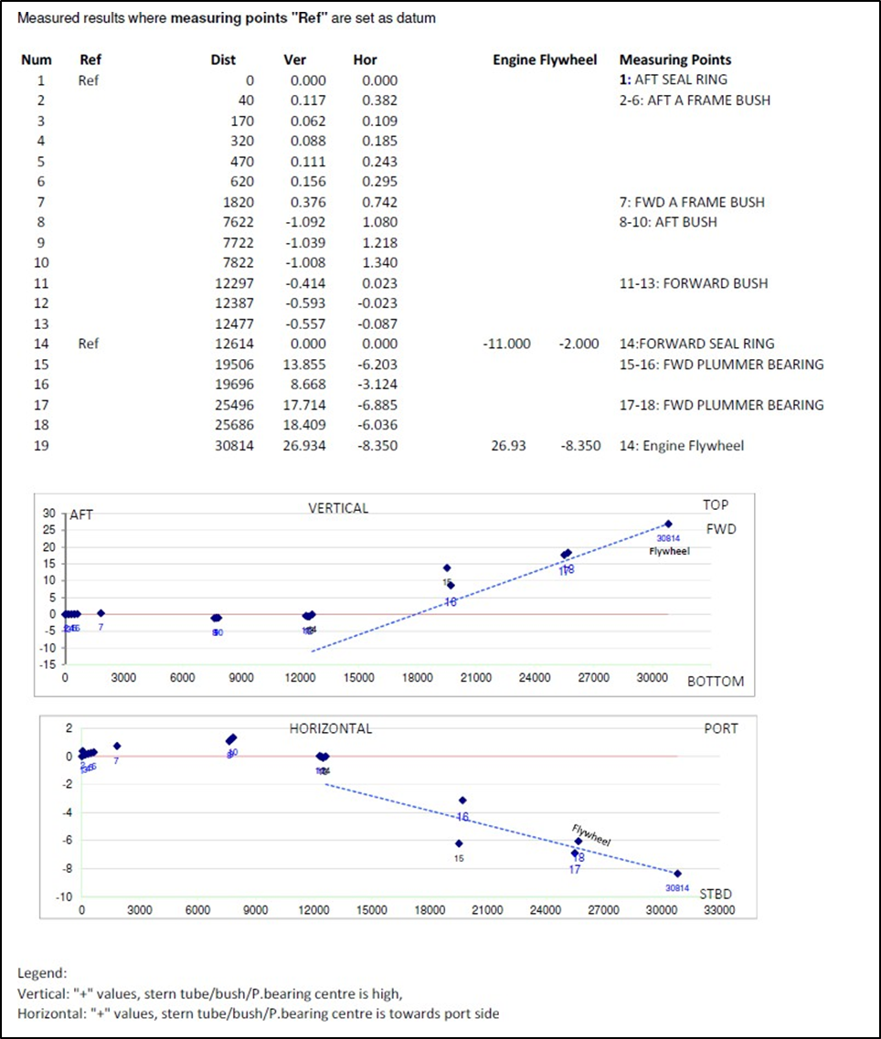
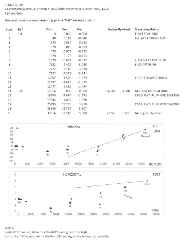
Post-incident measurements of the alignment of both propeller shafts
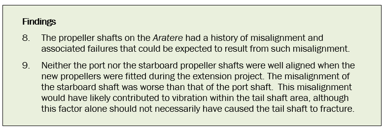
- In 2014, after the incident, KiwiRail sent the Aratere to dry-dock to replace the broken tail shaft and refit the old propellers. KiwiRail also took the opportunity to ensure that the alignment of the propeller shaft and gearbox was correct. Both propeller shafts were misaligned, with the starboard shaft showing a greater degree of misalignment than the port shaft. The starboard shaft would therefore have been likely to have more vibration than the port shaft.
- Measurements of the starboard propeller shaft alignment showed that the section of propeller shaft between the gearbox and the stern-tube was well aligned and the section of tail shaft between the propeller and the stern-tube bush was also well aligned. However, these two separate sections were not well aligned with each other. In other words, there was an error in the overall alignment of the propeller shaft between the gearbox and the propeller.
- Overall, the shaft was out of alignment with the gearbox by approximately 27 mm vertically and 8 mm horizontally (see Appendix 4 for full details). The misalignment was most pronounced between the section of the propeller shaft forward of the stern-tube bush and the tail shaft aft of the stern-tube bush. The misalignment was most likely a consequence of attempting to align the entire propeller shaft without withdrawing the tail shafts.
- Measurements of the port tail shaft alignment showed that the shaft was also out of alignment with the gearbox by approximately 23 mm vertically and 6 mm horizontally (see Appendix 4 for full details).
- The misalignments on both propeller shafts would have:
- increased the load on the propulsion motors and generators, because more power was required to rotate the shafts
- increased load on the bearings (damage was found on both aft-stern tube bearings)
- increased vibration.
- Three events suggest there was increased vibration in the shafting:
- an increase in accelerations within the starboard gearbox, which occurred some time after March 2012. A KiwiRail technician on the Aratere detected the increase during the vibration readings that they took quarterly. Until this point the technician had not detected any increase in vibrations since the Aratere had been lengthened in 2011
- the failure of one coupling between the starboard gearbox and one propulsion motor
- a tear appearing in the coupling between the same (starboard) gearbox and the other propulsion motor.
- The second and third events were indicative of a problem with the propeller shaft arrangement.
Did the weight and balance of the propeller cause uniaxial bending forces?
Weight
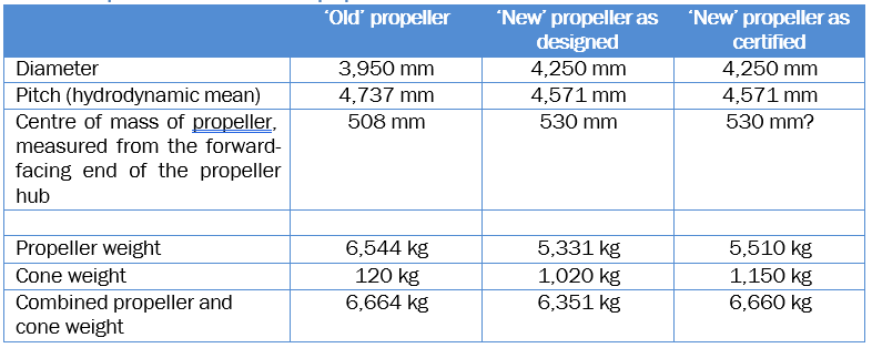
- The new propellers fitted to the Aratere in 2011 during the extension project were lighter than the old ones (see Table 2). The propeller cone was modified to accommodate this change, and became heavier as a result. The Commission was unable to determine whether the greater weight of the propeller cone contributed to increased vibration in the propeller shaft because KiwiRail did not carry out torsional or vibration calculations.
- In December 2010, during the planning phase for the extension project, Wärtsilä advised KiwiRail that, because of the decreased weight of the new propellers, the aft stern-tube bearing would have to be modified. Wärtsilä advised that the modification would ensure that the load on the bearing remained the same as with the original propellers, but the procedure required the tail shafts to be removed.
- KiwiRail decided not to remove the tail shafts and did not include their removal in the dry-dock specification. KiwiRail requested that Wärtsilä find another way to ensure that the same loading on the bearing was achieved.
- Wärtsilä offered two options. The first was to redesign the ‘new’ propeller to be the same weight as the ‘old’ propeller. However, the efficiency gain would have been about 0.8% less than Wärtsilä’s original design, and this option would have incurred a time delay and possible additional design costs. The second option, which KiwiRail took, was to increase the size and weight of the propeller cone to give the same bearing load as before.
- Wärtsilä designed a modification to the propeller cone, increasing the weight of the cone from the original 120 kilograms (kg) to 1,020 kg. This resulted in the same bearing load as the original propeller and cone. However, due to the increased weight of the propeller cone Wärtsilä advised KiwiRail to complete a new torsional and vibration calculation. Wärtsilä had not included such a calculation in its original cost estimate. KiwiRail made no request to Wärtsilä (or any other expert) to undertake a torsional and vibration calculation.
Balance
- If the propeller cone was either unbalanced or fitted at an angle to the face of the propeller hub, such that the centre of mass was not aligned with the shaft and propeller, this would have caused increased vibration. This could have been a minor contributing factor to the overall vibration in the propeller shaft. However, the Commission could not determine whether the propeller cone was unbalanced or fitted at an angle.
- The question of whether the propeller cone was balanced or not arose because of the discovery of a rubber gasket inserted in the joint between the cone and the hub. The propeller cone was designed to mate with the back of the propeller hub and was designed with an ‘O’ ring seal. The inclusion of the rubber gasket in the joint would have made tensioning the stud bolts to the correct torque more susceptible to error because of the compression of the rubber seal. Had one part of the seal been more compressed than the rest, the cone may have been at a slight angle to the hub, possibly inducing vibration.
Stress loading on the tail shaft from the propeller
Introduction
- The fatigue crack in the starboard tail shaft developed just within the leading edge of the propeller hub. As mentioned previously, a certain amount of stress is required for a fatigue crack to form and propagate through the tail shaft. Consequently, the performance of the starboard propeller was a significant focus for the Commission.
- The fatigue crack’s origin was between the roots of blades C and D in line with the trailing edge of blade C (Quest Integrity Group (2015) Aratere Starboard Propeller Shaft Failure Investigation, section 3.1).
- Typical stressors that initiate and drive the type of fatigue crack seen in the Aratere’s tail shaft are those that cause uniaxial bending of the tail shaft. Uniaxial bending can be caused by uneven thrust between the individual propeller blades. All blades on a propeller will produce uneven thrust as they rotate through the wake field coming off the stern of the ship. The amount of uneven thrust can vary if there is an appreciable difference between the average pitch of each blade. It can also vary if cavitation causes each blade to operate at a different efficiency.
- Cavitation is when cavities (bubbles) of vapour form in a liquid at low pressure; when the pressure increases the bubbles implode. These implosions can cause intense shock waves that are capable of causing cyclic stress and surface fatigue if near to a metal surface. A distinct erosion or ‘orange peel’ effect on metal surfaces will often be visible, and this was observed on the Aratere’s starboard propeller (see Figure 10). Where cavitation occurs over a large area, a significant load can occur and can introduce a flutter-type vibration to the blade (Quest Integrity Group (2014). Aratere Starboard Propeller Shaft Failure Investigation, page 22/55).
- When designing ships, naval architects anticipate forces from uneven thrust and cavitation, and tail shafts should be able to withstand these forces. However, if a tail shaft is in a weakened state through fretting or corrosion, as was the case for the Aratere, such forces can initiate and propagate a fatigue crack.
- Consequently, variations in the average pitch between individual propeller blades and the effects of cavitation are considered in the following sections.
Uniaxial bending as a result of variation in propeller blade pitch
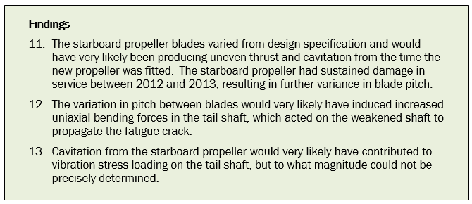
- The blades on the ‘new’ starboard propeller as manufactured had deviated from the design pitch (as illustrated in Appendix 3). Although the differences were within the relevant ISO (International Organization for Standardization) standard tolerances, it is likely that this variance in pitch produced uneven thrust and cavitation from the time the propeller was fitted.
- Following the recovery of the starboard propeller, multiple experts examined it and Aurecon laser-scanned and measured it. The propeller had sustained damage that had altered the pitch of all four of its blades and the pitch varied from the as-built pitch (see Appendix 3). The extent of variation was different for each blade: blade A had the largest difference between the manufactured and post-incident pitch; blade B had less difference in pitch; blade C had less again; and blade D had the least difference in pitch.
- DNV, as the vessel’s classification society, surveyed the Aratere annually and had noted damage to the starboard propeller blades during a July 2013 in-water survey. This damage had not been seen in an August 2012 survey so DNV determined that the damage had occurred sometime between August 2012 and July 2013. The damage sustained by the blades of the starboard propeller was likely to have induced increased uniaxial bending forces on the propeller and shaft.
- The tail shaft had fatigue cracks that corresponded with blade A, directly opposite the origin of the main fracture, which corresponded with the trailing edge of blade C (Quest Integrity Group (2015) Aratere Starboard Propeller Shaft Failure Investigation, section 3.3). This would suggest additional bending forces on the tail shaft. However, as previously mentioned, these bending forces would not usually cause fatigue cracking without the surface of the shaft having first been weakened by corrosion and fretting. It is very likely that the variation in blade pitch was a significant factor in propagating the fatigue crack once it had been initiated.
Cavitation as a result of variation in propeller blade pitch
- The ‘cavitation number’ of a propeller indicates the degree of cavitation from a propeller or its tendency to cavitate. The lower the cavitation number, in general, the more likely the propeller is to cavitate under certain operating conditions. But any deviation from the ‘as-designed’ propeller could make the propeller more susceptible to cavitation.
- According to the initial design study produced by Wärtsilä, the Aratere’s new propellers had a lower cavitation number than the old ones. Thus the ‘new’ propellers were operating closer to the point of cavitation than the ‘old’ propellers.
- Erosion from cavitation was seen on the rudders at the first dive survey following the fitting of the new propellers on the Aratere (Aurecon Final Report Page 1). The blades on the ‘new’ starboard propeller as manufactured had deviated from the design pitch (as illustrated in Appendix 3), so it is likely that they were cavitating to some degree from the time the propeller was fitted (Aurecon Final Report Page 1).
-
The design of the propeller meant that a relatively small amount of damage or deviation from the designed pitch could significantly affect the amount of cavitation from a blade. Blade C of the starboard propeller showed more damage and a greater degree of cavitation erosion than the other blades (see Figure 10 and section 9.4 Extent of cavitation scouring on the rudders). The observed damage and erosion indicated that blade C could have induced a greater vibration load on the tail shaft. Quest noted (Quest Integrity Group (February 2014). Aratere Starboard Propeller Shaft Failure Investigation, section 4.2):
Cavitation damage [erosion] was seen on all the blades on the recovered propeller to some extent. This indicates that the blades are probably designed to operate close to the operational region where cavitation will occur. This was as reported in the design of the blades. As a result, it may be possible that relatively small changes in the blade shape could make significant changes to the cavitation seen on a blade.
-
The extent of cavitation erosion on the port propeller was less than that on the starboard propeller. When KiwiRail dry-docked the vessel in Singapore after the incident, Quest reported (Quest Integrity Group (2014). Aratere Starboard Propeller Shaft Failure Investigation, report 105323.04. page 25/112):
The amount of suction surface cavitation pitting [erosion] on the port propeller was significantly less than seen on the starboard propeller … The extent of cavitation was similar to the profile predicted by Wartsila in report TDH 000003044. [See the diagram at the top of Figure 11, this report.]
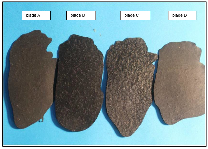
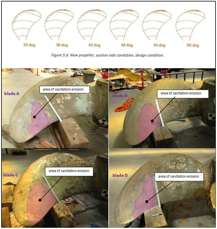
- The areas of cavitation erosion generally coincided with the areas of difference between the as-designed and the recovered propeller, including the damage sustained between 2012 and 2013 (see Figure 11). The variation in the patina strongly suggested that, at some stage, the flow pattern around blade C had been significantly different from the flow pattern around the other blades. If a resonant flutter had occurred in blade C as a result, this could have caused vibration stress in the shaft and explained the location of the fatigue crack’s origin (Quest Integrity Group (2014). Aratere Starboard Propeller Shaft Failure Investigation, report page 22/55).
-
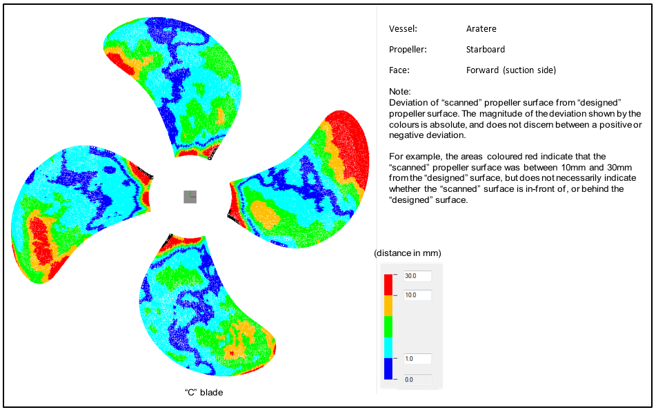
Aurecon produced a three-dimensional laser surface scan of the propellers (see Figure 12). KiwiRail engaged MARIN to analyse the propeller forces and cavitation. MARIN’s analysis sought to calculate what cavitation would have resulted from the damaged propellers. MARIN concluded:
The observed erosion pattern on the propeller blades would suggest the presence of a diverging trace of bubbles originating from the leading-edge. A narrow ‘isolated’ band of sheet cavitation or a cavitating vortex is expected that is being shed from the leading-edge. The results of the calculations show no traces of such narrow cavitation patterns starting from the leading-edge…(MARIN (2015), KiwiRail ‘Aratere’ Ferry Propellers: Analysis of propeller forces and cavitation, page 12 para 3.2.3)
… The location and shape of the computed sheet cavitation pattern cannot be linked to the observed damage on the starboard propeller blades…(MARIN (2015). KiwiRail ‘Aratere’ Ferry Propellers: Analysis of propeller forces and cavitation, page 14, May 2015)
… The calculations did not capture the supposed erosive cavitation forms that are likely responsible for the observed erosion damage. This could be due to limitations to the applied calculations procedure, the representation of the propeller blade geometry and the assumed wake field of the ship (MARIN (2015). KiwiRail ‘Aratere’ Ferry Propellers: Analysis of propeller forces and cavitation, page 14, May 2015).
- MARIN’s analysis was not useful for explaining the cavitation erosion observed on the propellers and rudders. MARIN acknowledged this was probably because the computer model was unable to map the propeller accurately or accurately predict the effects of the wake field coming from the stern of the ship (MARIN (2015). KiwiRail ‘Aratere’ Ferry Propellers: Analysis of propeller forces and cavitation, page 14, May 2015).
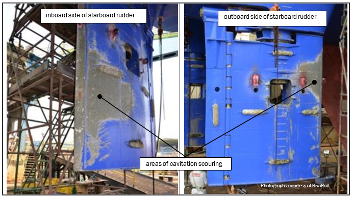
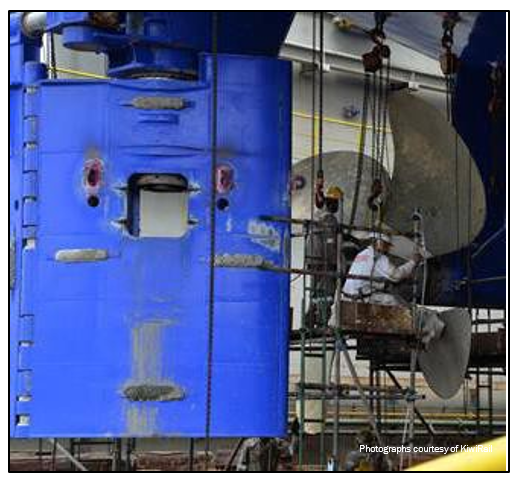
Extent of cavitation scouring on the rudders
-
When the Aratere dry-docked in Singapore it was found that the paint had scoured from the surface of the rudder in two distinct areas (see Figure 13 and Figure 14). This scouring was characteristic of the effects of cavitation from the propeller.
- The Commission reviewed the recordings from DNV’s in-water surveys carried out between the fitting of the ‘new’ propellers and the incident. Cavitation scouring of the paint on the starboard rudder was evident in both recordings, which further suggested that the starboard propeller had been cavitating from the time it had been fitted.
- Cavitation scouring was also present on the port rudder but not to the extent seen on the starboard rudder.
Cumulative effect of forces acting on the Aratere’s starboard propeller shaft
- In its Final Report, Aurecon placed significant weight on the manufacturing of the propeller (in particular a malformed blade C) as the primary cause of the fatigue crack. The Commission determined that the new starboard propeller blades had been producing uneven thrust and cavitating from the time the propeller had been fitted. However, the thrust and cavitation, by themselves, were unlikely to have been sufficient to propagate the fatigue crack.
- The DNV records showed that the starboard propeller had suffered damage while in service on some date between August 2012 and July 2013. The evidence showed that this damage resulted in a change in blade pitch for all four propeller blades. Blades A, B and C had all been within the ISO tolerances when the propeller was built. However, when measured after the incident all three blades were found to be well outside the ISO tolerances (see Appendix 3). The areas of cavitation erosion seen on all four blades (Figure 11) generally coincided with the areas of difference in pitch between the propeller as it had been designed and when it was recovered after the incident, which makes it almost certain that the damage occurred in service, and not as a result of the incident.
- It is very likely that the in-service damage to the propeller induced greater uniaxial bending forces. Also, it is very likely to have increased the cavitation and the consequential increase in vibration stress loading on the tail shaft.
- In isolation, uneven thrust and cavitation should not result in catastrophic fatigue cracking in tail shafts, but the Aratere’s starboard propeller shaft was in a weakened state as a result of fretting and corrosion. Uniaxial stress loading on the tail shaft would have likely increased following in-service damage and, combined with cavitation, acted on the weakened shaft to propagate the fatigue fracture until complete failure
ISO standards for manufacturing tolerances
The manufacture of the Aratere propellers
- One of the most important factors in manufacturing a marine propeller to perform as predicted is to reproduce the shape in the original design as closely as possible. Manufacturers can use two methods to shape propeller blades: hand finishing or computer numerical control machines. The latter usually provides a more accurate finish.
- Wärtsilä manufactured and hand finished the propellers that were fitted to the Aratere to within the tolerances of ‘ISO standard 484/1-1981 Class I, high accuracy’ (Class S, ‘very high accuracy’, was the only higher class of accuracy). So, for example, on the Aratere’s propellers with a mean pitch (The pitch is the distance a propeller would move in one revolution if it were moving through a soft solid, like a screw through wood. For example, a 21-pitch propeller would move forward 21 units in one revolution) of 4,571 mm, a tolerance of plus or minus 1.5% at each radius meant the propellers’ actual pitch could be up to 68 mm different from the designed pitch and still be ‘within tolerance’. The propellers’ mean pitch is only allowed to deviate up to 0.75% from the designed value.
- As previously mentioned, the ‘cavitation number’ indicates the degree of cavitation on a propeller or its tendency to cavitate. The lower the cavitation number, in general, the more likely the propeller is to cavitate under certain operating conditions (Eisenberg, 1950). But any deviation from the ‘as-designed’ propeller could make the propeller more susceptible to cavitation.
- According to the initial design study produced by Wärtsilä, the Aratere’s ‘new’ propellers were designed for higher efficiency and thus had a lower cavitation number than the ‘old’ ones. Thus the ‘new’ propellers were operating closer to the point of cavitation than the ‘old’ propellers under normal operating conditions.
ISO standards
- The ISO sets standards for the manufacturing tolerances of the type of propellers that were fitted to the Aratere. The relevant ISO standard is ‘Standard 484/1 Shipbuilding – Ship screw propellers – Manufacturing tolerances – Part 1: Propellers of diameter greater than 2.50 m’ (referred to in this report as ‘ISO standard 484/1’).
- ISO standard 484/1 came in to force in 1981. It set four accuracy classes, which were to be selected by the customer. Several tables set out the indications as to the accuracy (see Appendix 2 for full details). However, propeller design and manufacture has evolved since 1981. Propellers have become more efficient. However, as a propeller’s efficiency increases it operates closer to the point where it would cavitate. These high-efficiency propellers therefore require high-accuracy manufacture with small tolerance limits to ensure that performance is maintained and they do not cavitate. It is possible that the tolerances contained in ISO standard 484/1 are too wide for modern, high-efficiency propellers.
- The Commission has made a recommendation to Standards New Zealand to forward the report to the ISO Secretariat for its information on whether the current standards for manufacturing large-diameter marine propellers are appropriate for modern, high-efficiency propellers that operate closer to cavitation margins.
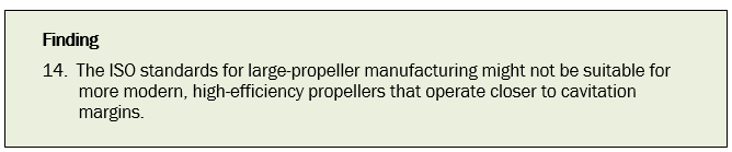
Other matters
Rudder stock cracking
- As described above, in 2014 KiwiRail dry-docked the Aratere after the incident to refit the old propellers. While it was in dry-dock, KiwiRail found cracks in the starboard rudder stock.
Examination of rudder stocks in dry-dock
- While the Aratere was in dry-dock after the incident, the port and starboard rudders were removed so the tail shafts could be removed and refitted. When the tail shafts had been reinstated and the rudders were about to be refitted to the rudder stocks, a crack was observed on the starboard rudder stock (see Figure 15). Further investigation found the rudder stock was cracked horizontally on both the outboard and inboard faces. An examination of the port rudder stock showed it was also cracked, but to a lesser extent.
- KiwiRail had to replace the starboard rudder stock because the cracks were of a depth that could not be repaired. KiwiRail decided to replace the port rudder stock also, even though it could have been repaired.
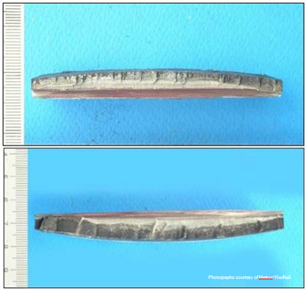
Cause of the cracking
- KiwiRail engaged Matcor to determine the cause of the cracks found in both rudder stocks, with an emphasis on the starboard stock.
- Matcor determined that because of their position and depth, the cracks were most probably linked to the forces applied to the starboard rudder by the cavitation from the starboard propeller (see Figure 14), rather than any defects in the structure of the metal. These forces were likely to be outside those expected in normal operations.
-
Matcor stated that the fracture surfaces of the cracks in the starboard rudder stock were (Matcor (2014). Report 14115 – Condition Assessment of Starboard and Port Rudder Shafts of Vessel ‘MV ARATERE’):
generally flat with multiple fracture initiation sites along the shaft surface. Fractographic examination revealed that the fracture surface was generally smeared and corroded. At some areas towards the crack tip, faint traces of striations could be discerned. The fracture features were generally consistent with fatigue crack propagation.
- Quest agreed that the castellations on the cracks (see Figure 15) showed that the cracks had formed due to separate smaller cracks joining together. The crack was a multi–origined fatigue failure where the forces applied were well above the fatigue limit. The crack may have stopped at the depth it reached due to the smaller diameter of the shaft, because a smaller-diameter shaft needs more force applied to cause a crack. The orientations of the cracks on the starboard shaft were indicative that it was being forced from side to side (Record of telephone conversation with Quest representative).
- Quest determined, from an examination of the photographs of the rudder stock’s metal structure, that there did not appear to be any defects in the structure of the metal.
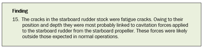
Oversight of the fitting of new propellers
- The replacement of the Aratere’s propellers was a modification to one of the ship’s critical systems. The Commission found that advice from appropriate experts was either not sought or not followed during the fitment operation to ensure that the propulsion system had been set up and functioning properly before the vessel re-entered service.
Expert advice
- In investigating the fitting of the new propellers, the Commission found examples of KiwiRail not following expert advice.
- One example concerned KiwiRail’s decision to not follow Wärtsilä’s original advice to withdraw the tail shafts to modify the tail shaft bearings as a result of the lighter propellers. KiwiRail’s decision to not withdraw the tail shafts led to the need to modify the propeller instead, and prevented its own propeller expert achieving full alignment of the tail shaft.
-
A second example was KiwiRail’s decision to not follow Wärtsilä’s advice to carry out torsional and vibration calculations before fitting the new propellers. With respect to torsional vibration in propulsion systems, DNV wrote (DNV-GL, 2016):
Keeping control of vibration levels in your engines, propulsion systems and generator sets is essential in order to have machinery that operates safely and reliably. The wrong combination of individually satisfactory components may lead to an inappropriate system. The Torsional Vibration calculation software can identify the interaction between components, an essential part of the system and functionality assessment.
- Wärtsilä had advised KiwiRail to carry out torsional and vibration calculations before fitting the new propellers, but the Commission found no evidence that this was done. Wärtsilä carried out torsional and vibration calculations after the incident, and concluded, “The torsional stress and torque amplitudes are well within allowable levels in normal operation”.
- When Wärtsilä designed the new propeller cone mentioned in previous sections, it again advised KiwiRail that a new torsional and vibration calculation would be required. KiwiRail wrote to Wärtsilä advising that it had asked its own propeller expert to carry out the torsional and vibration calculation. KiwiRail was unable to produce those calculations.
Documentation
- The replacement of the Aratere’s propellers was part of a wider project to lengthen the ship and modify its bow and stern to improve sea-keeping characteristics. The fitting of new propellers was only a part of this wider project; nevertheless, a ship’s propulsion system is a critical one. It is complex, made up of many components that must be compatible for the system as a whole to work efficiently and safely.
- Given the complexity of propeller replacement and the critical nature of the propeller system, the Commission expected to be provided with records of KiwiRail’s decision-making process and technical documentation prior to and during the fitment of the new propellers. However, KiwiRail was unable to provide documentation for:
- the decision-making process to re-propeller the Aratere
- the design brief
- specifications and standards for the propellers (other than the design proposed by Wärtsilä)
- verification that Wärtsilä’s design for the propeller was suitable for its intended use
- verification that a proper fit had been achieved between both propellers and the tail shaft, despite engaging the DNV classification society to observe the fitting.
- This lack of documentation from KiwiRail meant the Commission had no evidence that appropriate checks and balances had been in place to ensure that the new propellers were well fitted. As described in this report, the Commission considers it likely that several adverse conditions occurred in the Aratere’s starboard propulsion system shortly after the new propellers were fitted.
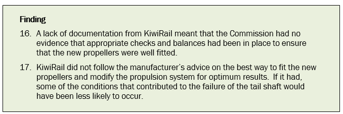
Summary
- Various experts concluded (Matcor (2014). Failure Analysis and Condition Assessment of Starboard and Port Propeller Shafts of Vessel ‘MV ARATERE’, section 4.3. Lloyd’s Register (2014). Metallurgical Investigation, section 2.2. Quest Integrity Group (2015). Aratere Starboard Propeller Shaft Failure Investigation, section 4.1) that the fracture that occurred on the Aratere’s starboard propeller shaft was a fatigue fracture, typical of that resulting from uniaxial bending forces. Such fractures begin with a crack in the surface of the metal that then propagates to the point where the metal can no longer withstand normal operating loads.
- For the crack to have initiated, the tail shaft must have been weakened. The Commission found clear evidence that fretting had occurred between the bore of the port and starboard propeller hubs and their respective tail shafts. This fretting, together with the presence of minor surface corrosion on both tail shafts, would have decreased the fatigue strength of the tail shafts, making them more susceptible to fatigue cracking due to uniaxial (bending) forces. The most likely reason for the fretting was the quality of the fit achieved between the propeller hubs and the tapered section of the tail shafts when the new propellers were fitted during the extension project in 2011.
- The Commission found it likely that the fit of the propellers was less than optimal, and that there was an increased risk of damage to contact surfaces. Any damage to the contact surfaces could have initiated fatigue cracking on the surface of the tail shaft. Any in-service movement resulting from the sub-optimal fit would have very likely caused the fretting.
- The main types of force acting on the tail shaft would have been uniaxial bending forces and vibration. These forces would have acted on the weakened tail shaft to propagate the crack. The Commission found measurable differences between the port and starboard propeller systems, showing that greater uniaxial forces were acting on the starboard propeller shaft.
- Measurable differences between the port and starboard propulsion systems that indicated increased vibration were:
- the misalignment of the entire starboard propeller shaft was worse than that for the port side
- the starboard propeller cavitation was worse than that of the port propeller
- the starboard propeller had been damaged in service, causing a further variation in average blade pitch (which would likely have increased cavitation on the starboard side).
- the starboard propeller cavitation was worse than that of the port propeller
- The Commission found no evidence of errors in design or manufacture or excessive forces acting on the tail shaft. Nevertheless, it fractured. None of the factors discussed in this report should, alone, have caused a well designed tail shaft maintained in good condition to fail. The tail shaft must therefore have been in a weakened state for the fatigue crack to initiate. Conversely, the tail shaft being weakened due to fretting and corrosion should not, alone, have caused the tail shaft to fracture. It required sufficient, albeit reduced, bending force to initiate the fatigue crack.
- In combination, the weakened state of the tail shaft and the levels of bending forces resulted in the failure of the tail shaft.
Appendix 1. Port and starboard shaft alignment problems
History of problems with port and starboard shafts
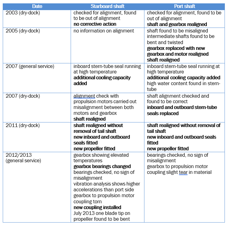
Appendix 2. ISO 484/1-1981 accuracy classes and tolerances
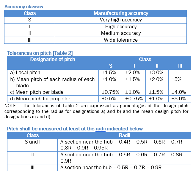
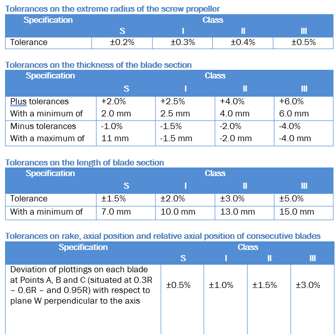
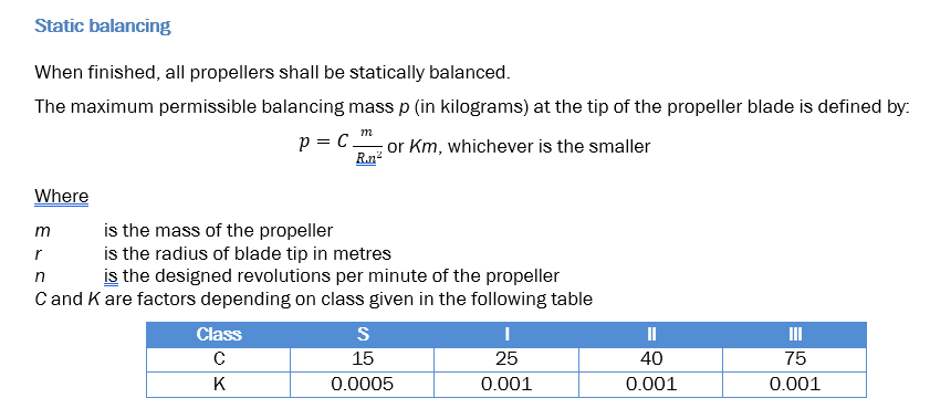
Appendix 3. Pitch dimensions and deviations, starboard and port propellers
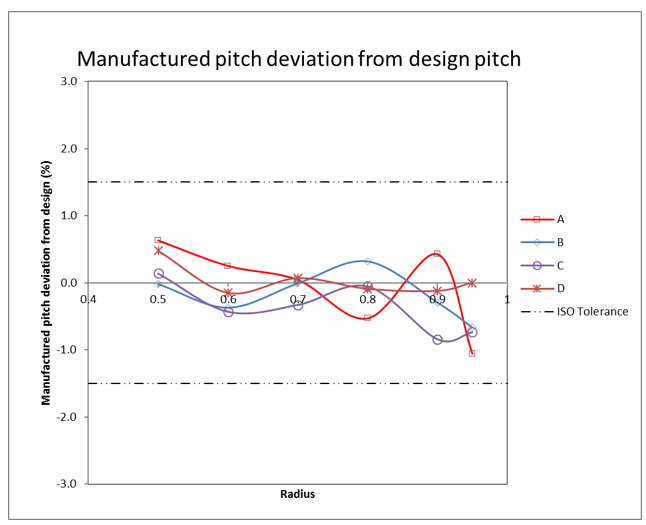
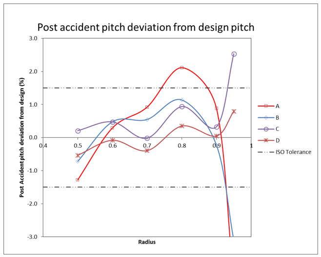
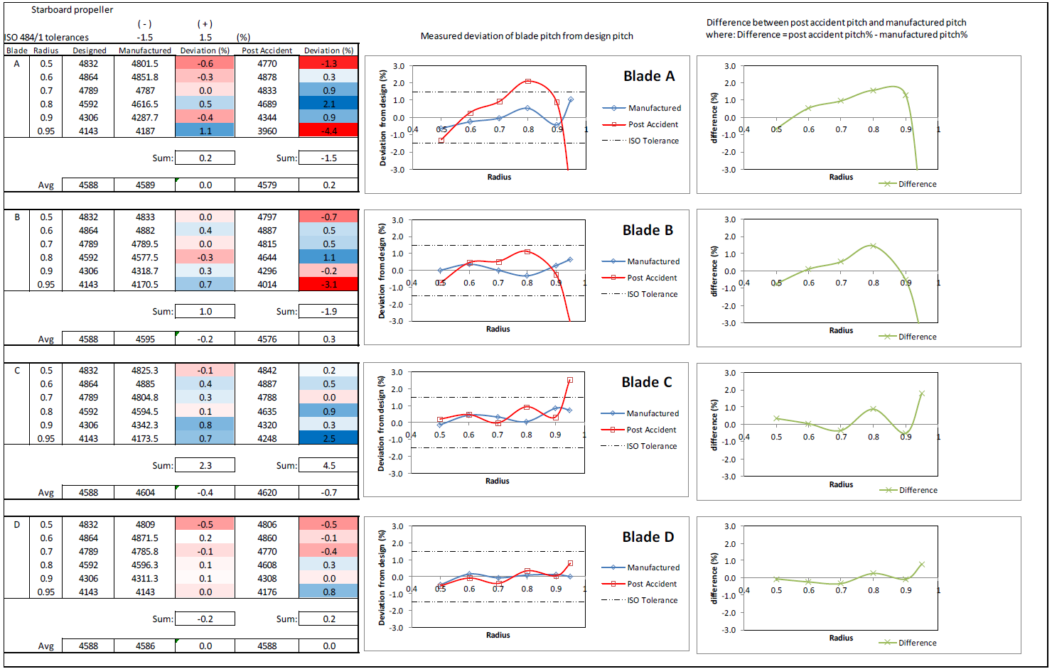
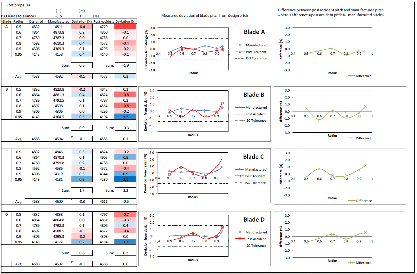
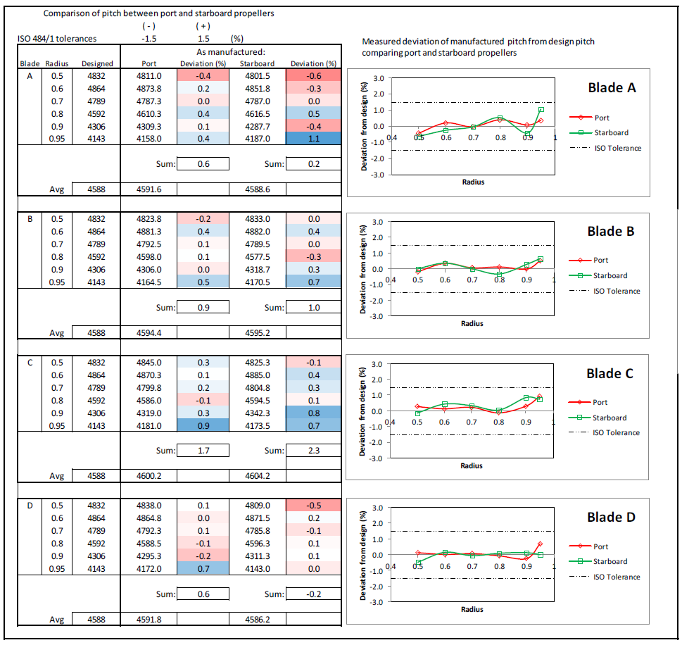
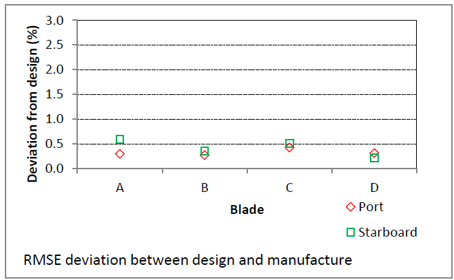
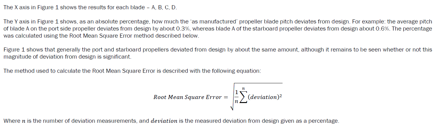
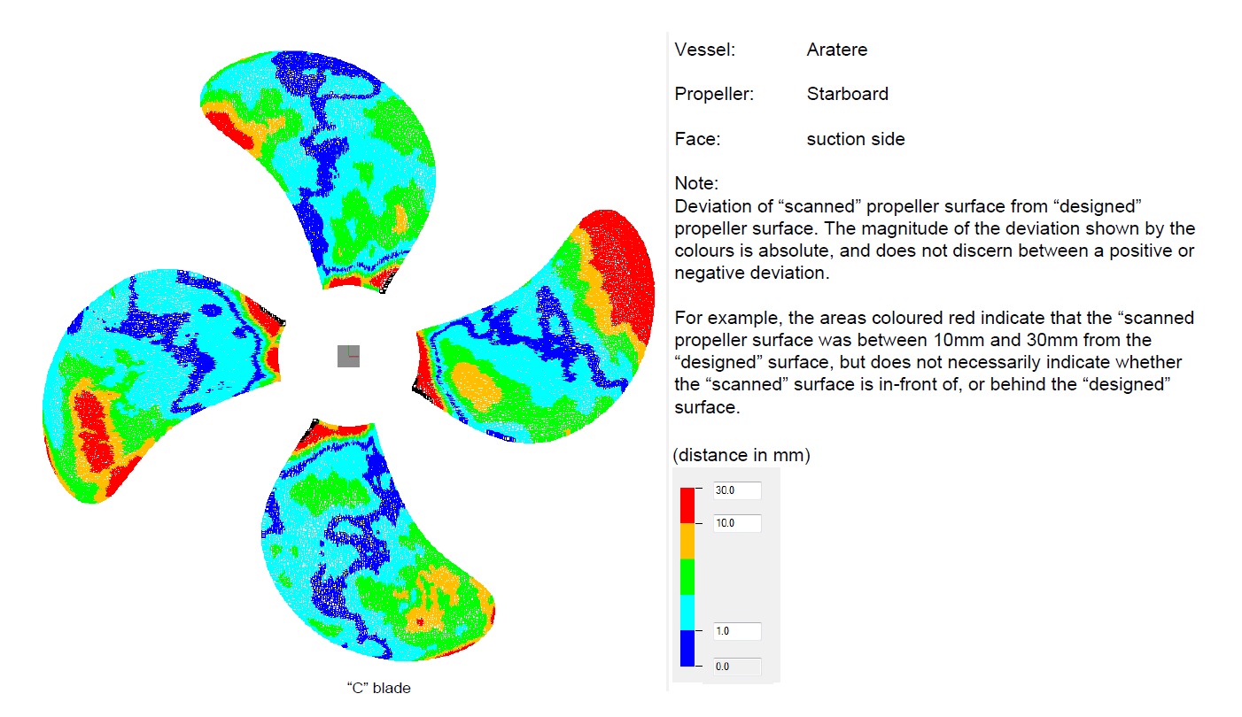
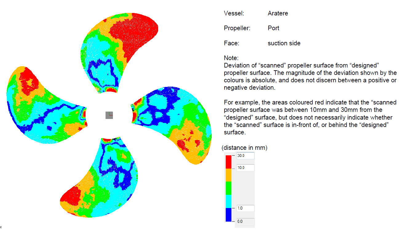
Appendix 4. Starboard and port shaft alignment – 7 March 2014