An Airbus A320 veered off a taxiway after landing. A hydraulic failure during the flight had disabled nosewheel steering and one engine’s thrust reverser. Uneven thrust sent the plane onto the grass. Nobody was injured, but one engine was significantly damaged. TAIC calls on Airbus to update manuals, and stresses careful inspection of high-pressure hydraulic parts.
Executive summary Tuhinga whakarāpopoto

What happened
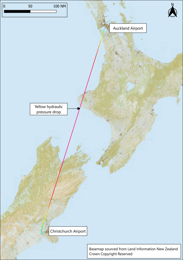
- On 31 May 2024, a Jetstar Airbus A320 flight from Auckland to Christchurch experienced a hydraulic failure in the cruise (the stage of flight between take-off and landing when an aircraft maintains a constant altitude and airspeed). The failure resulted in the loss of one of the three hydraulic systems.
- The flight crew followed standard operating procedures for this situation and, after assessment, continued to land at Christchurch. The nosewheel steering and number two (right side) engine reverser were disabled by the hydraulic failure. The flight crew were aware of these limitations and had planned to use differential braking (applying brake pressure to one main wheel (or set of wheels) more than the other, causing the aircraft to turn in that direction) to steer the aeroplane off the runway to avoid causing delays to following flights.
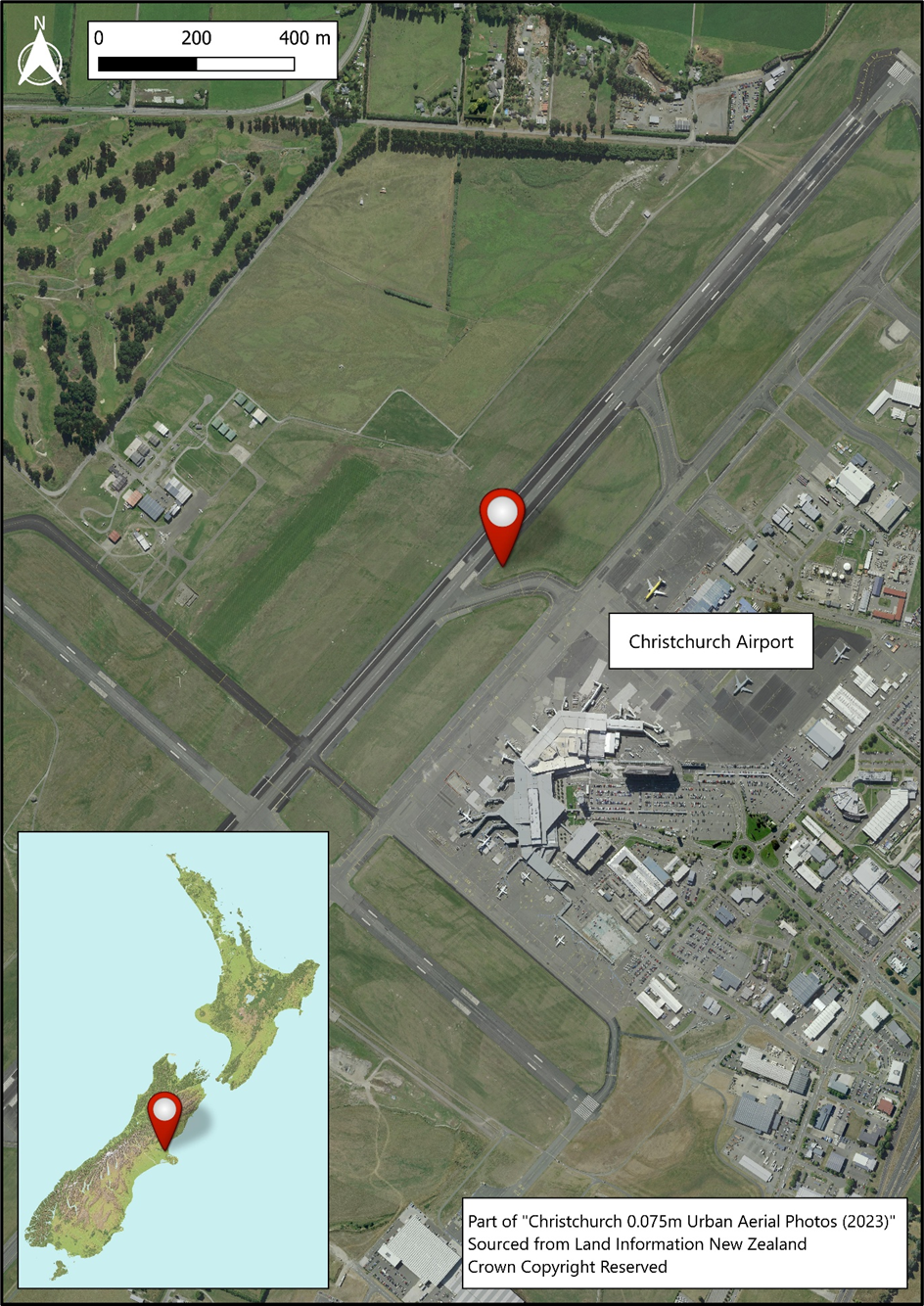
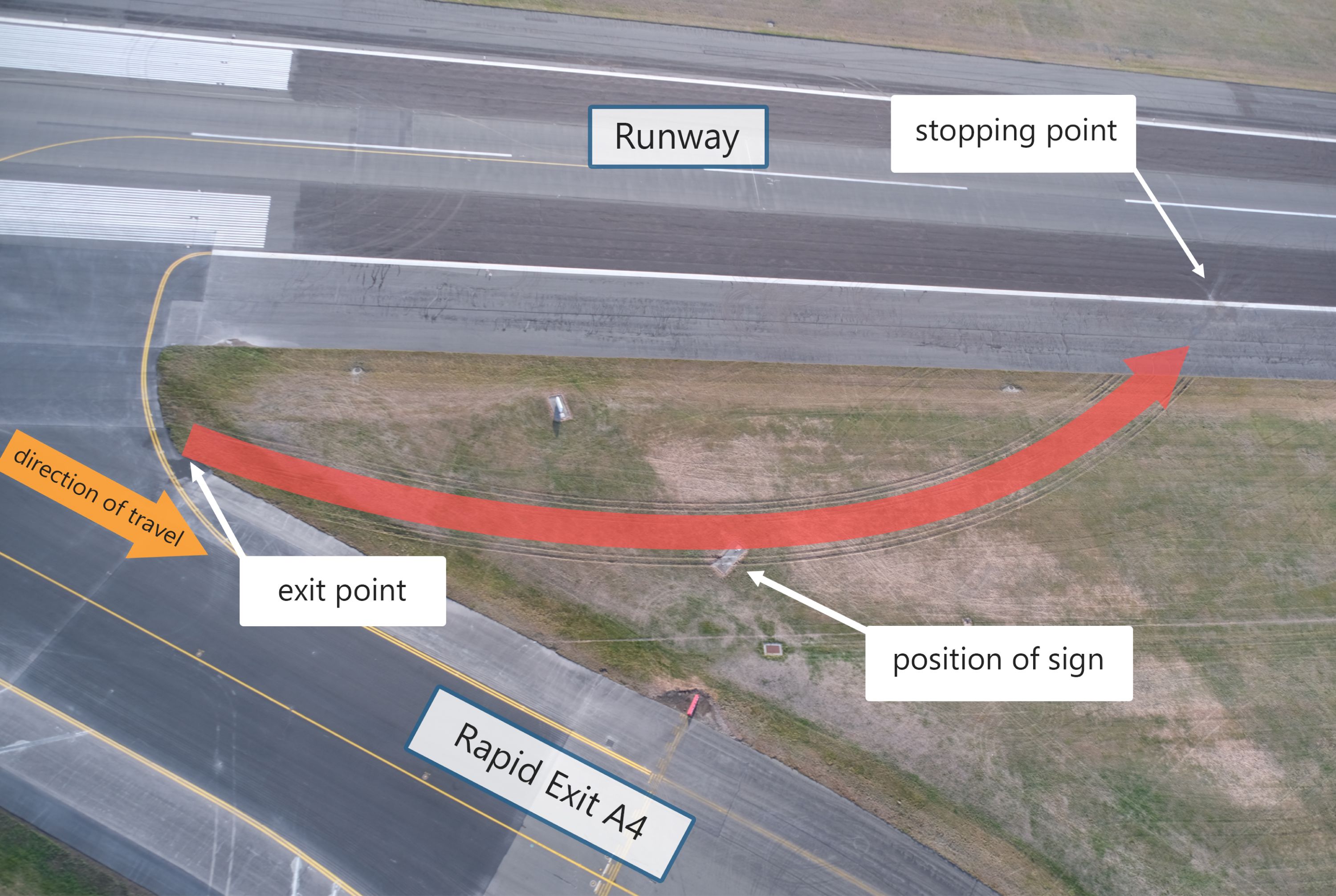
- The landing went to plan, but as the aeroplane entered the rapid exit A4 it left the sealed taxiway and ran onto the grass. It continued through an aerodrome signboard until it came to a stop on the edge of the runway.
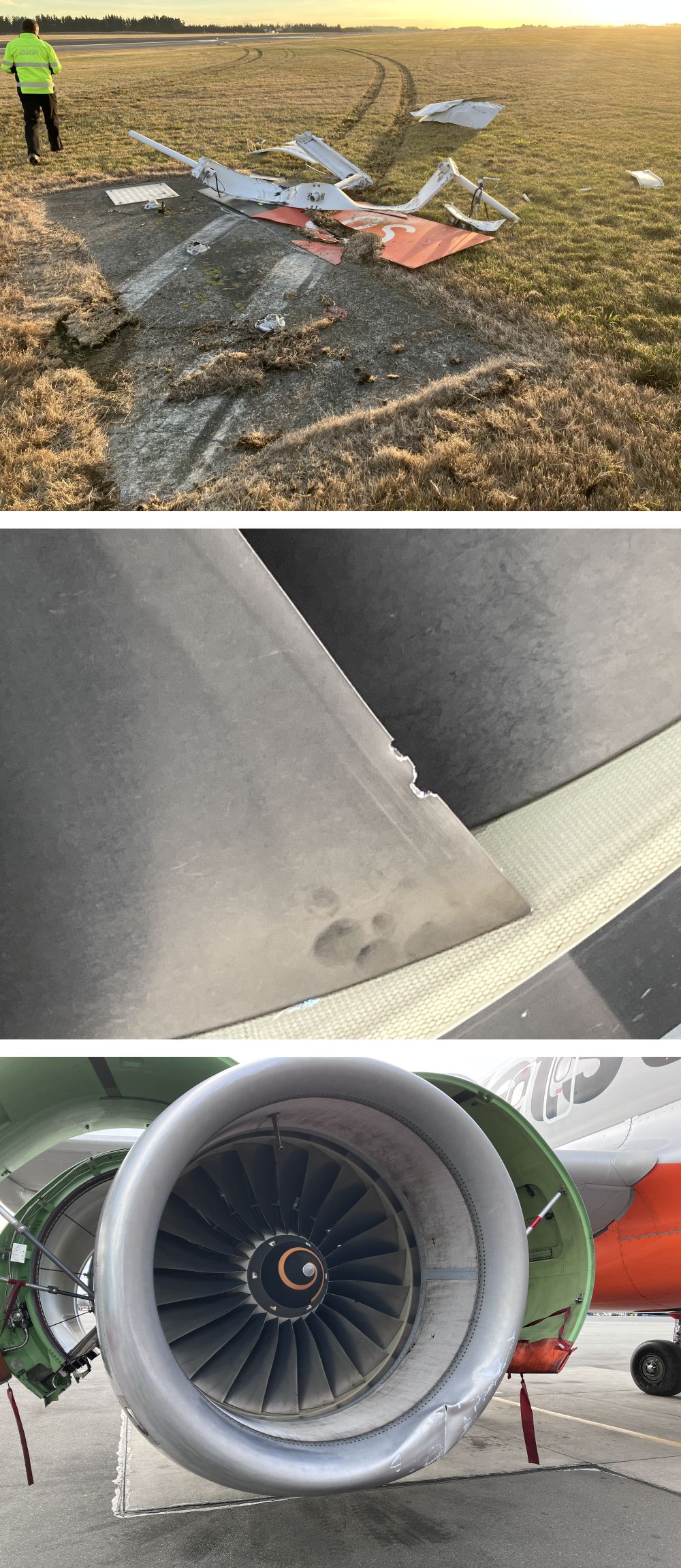
- No one was injured but the aeroplane suffered significant damage to parts of the number two engine as a result of hitting the signboard.
Why it happened
- The Commission found that the cause of the hydraulics system failure was a titanium pipe that had ruptured, leading to the loss of hydraulic fluid. The hydraulic pipe had failed due to overload stress on the inside surface at a deformed section of the pipe. The deformity was very likely caused when the new part’s packaging was damaged in transit between two Airbus parts warehouses in 2015, but had not been detected at the time.
- The aeroplane left the taxiway exit because the thrust levers were unintentionally moved to the CLIMB position rather than FWD IDLE and the flight crew did not detect or correct that error.
- The pilot was likely startled by the engines accelerating to CLIMB power and as a result pulled the thrust levers back into REV MAX (the range of thrust lever settings is explained in para 2.28). Engine No. 1 developed reverse thrust while engine No. 2 continued to provide forward thrust but at a reduced level. This was as a consequence of the yellow hydraulic system failure disabling the thrust reverser on that engine. This resulted in asymmetric thrust and an associated turning moment, with the pilot losing directional control of the aeroplane. The aeroplane ran off the taxiway to the left and onto the grass.
- At the time, the pilot was likely to have been under a high cognitive load and operating under conditions of stress. Both members of the flight crew were likely to have experienced attention tunnelling (the processing of highly critical task-relevant information with limited or no processing of secondary information that may also be important to the task), which precluded them from perceiving wider information, including the position of the thrust levers.
- The Commission found that when the flight crew used the rapid exit with nosewheel steering unavailable, this increased their cognitive workload and the risk of an incident.
What we can learn
- Any deformation on a high-pressure hydraulic pipe is a potential point of failure and requires a detailed inspection to ensure its serviceability.
Who may benefit
- Airbus A320 pilots, operators and aircraft maintenance engineers may benefit from the findings, recommendations and safety lessons in this report.
Factual information Pārongo pono
Narrative
- On 31 May 2024, Airbus A320 VH-VFF (the aeroplane) was operated by Jetstar Airways (the operator) as flight JST225 from Auckland to Christchurch with 175 people on board, including two flight crew and four cabin crew. At 0658 (times are stated in New Zealand Standard Time (NZST) which is Universal Time Coordinated (UTC) + 12 hours), as the aeroplane was south of Mount Taranaki at 36,000 feet (ft) (in New Zealand, in accordance with exceptions to the International System of Units and with the Aeronautical Information Publication (AIP) Gen 2.1, altitudes, elevations and heights are measured in feet. In this report these parameters are therefore only expressed in feet (ft) without a metric equivalent), the flight crew were alerted to a hydraulic system failure indication by the electronic centralised aircraft monitor (ECAM).
- The captain was operating as pilot monitoring (PM) and the first officer as pilot flying at the time of the alerts. In response to the alerts, the captain took over as pilot flying.
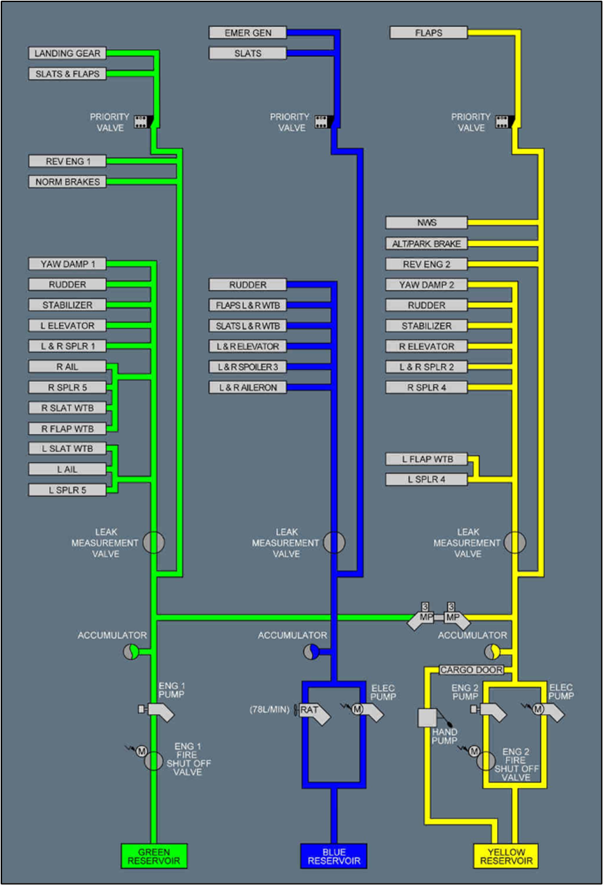
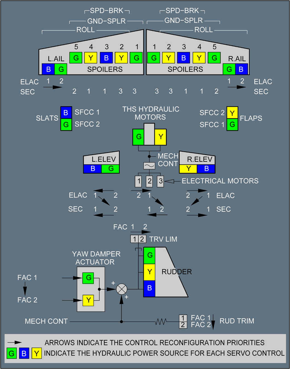
- The flight crew then followed the standard operating procedure (SOP) for ‘Abnormal’ situations as displayed on the ECAM. The ECAM provided guidance to the flight crew for a yellow hydraulics system (yellow hydraulic system is one of three on the aeroplane, and is explained further in paragraph 2.26) failure, helping them identify the problem and the aeroplane’s subsequent limitations due to the failure. The caution ‘Hydraulic, yellow, reservoir low level’ had a checklist of actions that the flight crew started to work through, including switching the yellow hydraulic pumps off. The ECAM also listed all the systems that had become inoperative as a result of the loss of hydraulic fluid (see Appendix 1 for the hydraulics system diagram).
- The fault indications showed that the yellow system had failed because of loss of hydraulic fluid. This had several consequences, including: the nosewheel steering would not be available to steer the aeroplane on the ground; the No. 2 (aircraft engines are named No. 1 and No. 2 rather than left and right to align with Airbus documentation) engine reverser would not be available to assist deceleration after landing; there would be fewer spoilers (devices on the wings that reduce lift after landing and assist the aircraft to remain on the ground) than normally available to reduce lift after touchdown; and the cargo doors and some other systems were affected.
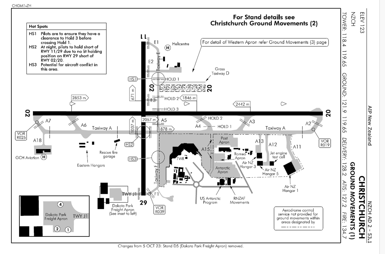
- The flight crew checked the landing distance at Christchurch Runway 02 and decided that they could exit the runway at the rapid exit (a shallow angled exit path from the runway that allows aircraft to exit at a reduced speed after landing but still be faster than a normal taxi speed) A4 (see Appendix 2 for the layout of Christchurch aerodrome). This would allow the aeroplane to clear the runway, but it would then need to be towed to the gate (term for the area where aircraft park to connect to an air bridge).
- The captain briefed the first officer on the plan. The flight crew reported the fault to the operator’s maintenance operations centre in Melbourne and to Jetstar Christchurch. The captain called air traffic control (ATC), explained their situation and requested a tow after the exit at A4. ATC informed Christchurch Tower, who advised the fire crew to stand by as the aeroplane landed in case of an emergency. The captain briefed the cabin manager.
- Just after the aeroplane started its descent, ATC advised all traffic that the active runway had changed to the reciprocal Runway 20 and that the automatic information broadcast had been updated (the automatic terminal information service (ATIS) broadcast information was updated to ‘Charlie’). After considering this change, the flight crew rechecked the landing distance for Runway 02 with a 10 knot (kt) tail wind. As it was still acceptable, with the predicted stopping point before rapid exit A4, the captain decided that they could continue to use Runway 02 and vacate the runway at rapid exit A4.
- They requested that ATC allow them to continue as planned on Runway 02. This was agreed, and the controller offered vector guidance to assist their navigation for that approach if they required, which the flight crew accepted.
- The approach was normal and met the operator’s stable approach criteria. The flight crew noted that the tail wind was less than what they had expected, and the wind direction changed over the last 1000 ft of the approach. The tower cleared them to land and advised that the wind was now 5 kt from 240 degrees (a tail wind from their left rear quarter). The auto callout RETARD (a synthesised voice system makes the callout of ‘RETARD RETARD’ when the aircraft passes 20 ft above the ground, and this prompts the handling pilot to close or retard the thrust levers to the idle position) occurred at 20 ft above the surface, and the captain pulled the thrust levers back to the FWD IDLE power setting, disconnecting the AUTO THRUST (this is a system to assist pilots to manage engine power during a flight) control.
- The aeroplane touched down at 149 kt and the spoilers deployed as expected. Just after touchdown, the captain armed the reversers (lifted the levers) and pulled both (Jetstar pilots were trained to operate both thrust levers together if they experienced an asymmetric reverser fault) thrust levers back past the FWD IDLE detent (a mechanical latching device that requires effort to move past) to REV MAX position.
- The reverser on engine No. 1 deployed and, as expected, engine No. 2 reverser did not deploy. The PM noted this and called, ‘Reverse green’.
- On the landing roll, the autobrake slowed the aeroplane until the captain applied manual braking near 75 kt ground speed. The manual application of braking disabled the AUTOBRAKE function as expected. They maintained alignment with the centreline using rudder and, as that lost effectiveness, used differential braking.
- The braking and partial reverse thrust were effective as the speed slowed and the PM called ‘DECEL’, indicating that the desired deceleration rate had been achieved. As the airspeed decreased below 70 kt, the PM made the standard call, ‘70 kt’. This is the minimum airspeed where REV MAX should be used and when the reverse thrust loses its effectiveness and should be reduced to REV IDLE.
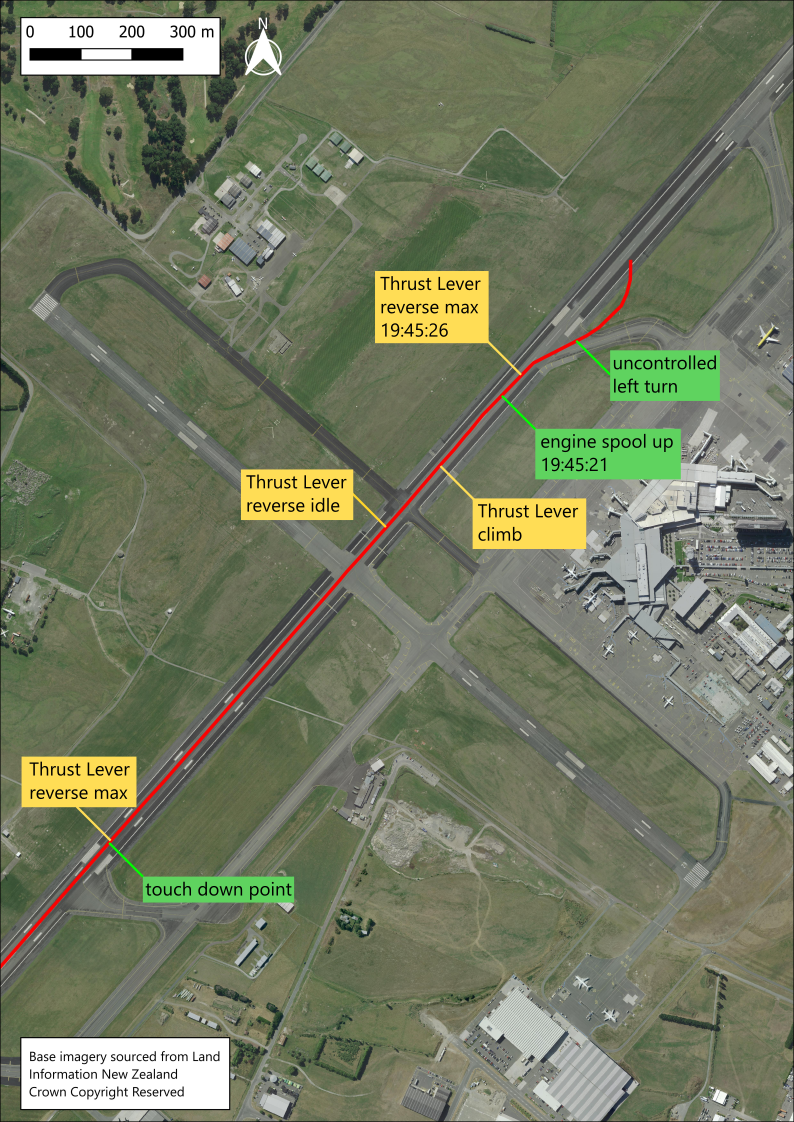
- The captain pushed the thrust levers forward to REV IDLE, then four seconds later through to the CLIMB detent, which stowed the left reverser. They turned off the runway towards rapid exit A4, at which point the flight crew heard the engines spool up (an increase in turbine engine rotational speed, producing an increase in thrust). The ground speed increased from 28 kt to 40 kt. In response, the captain pulled both thrust levers back to REV MAX.
- The engine No. 1 reverser deployed, but the engine No. 2 reverser was disabled due to the hydraulic failure and remained stowed. An ECAM warning stated that the No. 2 reverser was faulty. The aeroplane veered left off the rapid exit A4 onto the grass.
- The captain returned the thrust levers to FWD IDLE and applied full braking. The aeroplane continued to travel across the grass and came to a stop on the edge of the runway. The captain then applied the park brakes.
- The rescue fire service attended as was their standard practice and observed the aeroplane for signs of smoke or fire. They sought direction from the captain. After assessing the situation, the captain decided it was safe for passengers and crew to stay in the aeroplane. They advised the crew and passengers over the public address system what had happened and that they were safe.
- The flight crew started the auxiliary power unit (APU) to maintain electrical power within the aeroplane and shut down the engines. The aeroplane was towed to the gate.
- The flight crew remained on board and disembarked after the passengers.
Personnel information
- The captain had an Airline Transport Pilot Licence (ATPL) issued in Australia for aeroplanes, and their last operator’s pilot proficiency check was completed on 9 February 2024. Their total flying experience was 11,824 hours, with 6117 hours as pilot in command of A320 aeroplane and 105 hours in the last 90 days. They reported that they felt rested and alert on the day of the accident.
- The first officer had an ATPL issued in Australia for aeroplanes. Their total flying experience was 6011 hours, with 1211 hours on A320 aeroplane and 160 hours in the last 90 days. They reported that they felt rested after recent time off duty and alert on the day of the accident.
Aeroplane information
- The aeroplane was an Airbus A320-232 with two IAE V2527-A5 turbofan engines.
- The aeroplane was manufactured in March 2012. It was Australian registered and had a standard, non-terminating certificate of airworthiness issued by the Australian Civil Aviation Safety Authority for air transport category, dated 8 March 2012.
- The last maintenance carried out was a scheduled check completed on 19 March 2024 at 33,151 hours and 19,277 cycles. At the time of the accident, the aeroplane had completed 33,783 airframe hours (the total time an aircraft’s airframe has been in operation) and 19,554 take-off and landing cycles.
- The aeroplane had left Auckland in a serviceable condition but with several minor items of cabin equipment listed for deferred maintenance (these were listed in the technical log under Minimum Equipment List (MEL)). There were 169 passengers on board, two flight crew and four cabin crew.
Hydraulic systems
- The A320 has three separate hydraulic systems, identified as green, blue and yellow (see Appendix 1 for a schematic of the hydraulic systems). The control surfaces operated by hydraulics are arranged so that if any hydraulic system fails, the control surface can still be operated with one of the other two systems. Some devices considered less essential for flight are only operated by one of the hydraulic systems. For example, the yellow system operates the nosewheel steering and the cargo doors but there is no backup from the other hydraulic systems.
- A single hydraulic system failure in-flight is described by Airbus as being abnormal but not critical. The flight can continue but may have some restrictions or limitations.
Thrust levers
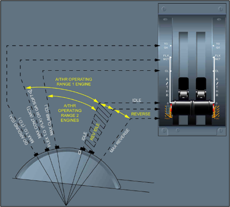
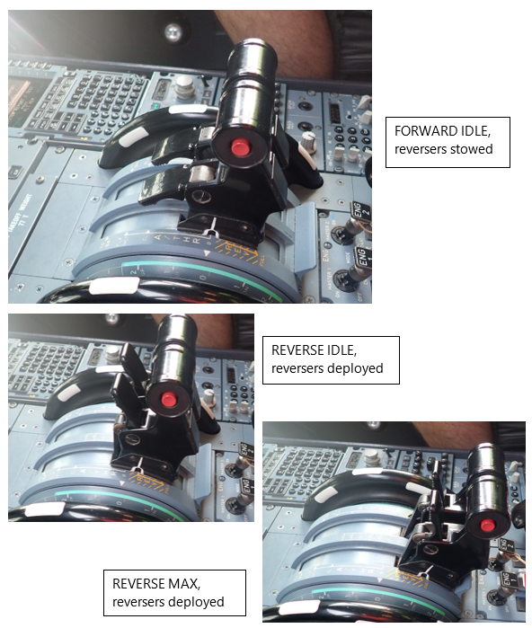
- Each of the engines is controlled by a full authority digital engine controller (FADEC), which takes its control inputs from the thrust levers that the pilot operates. The pilot sets the thrust level for the phase of flight, and the FADEC manages the fuel flow to maintain the selected power setting (see Figure 4 and Figure 5 for the different thrust lever positions).
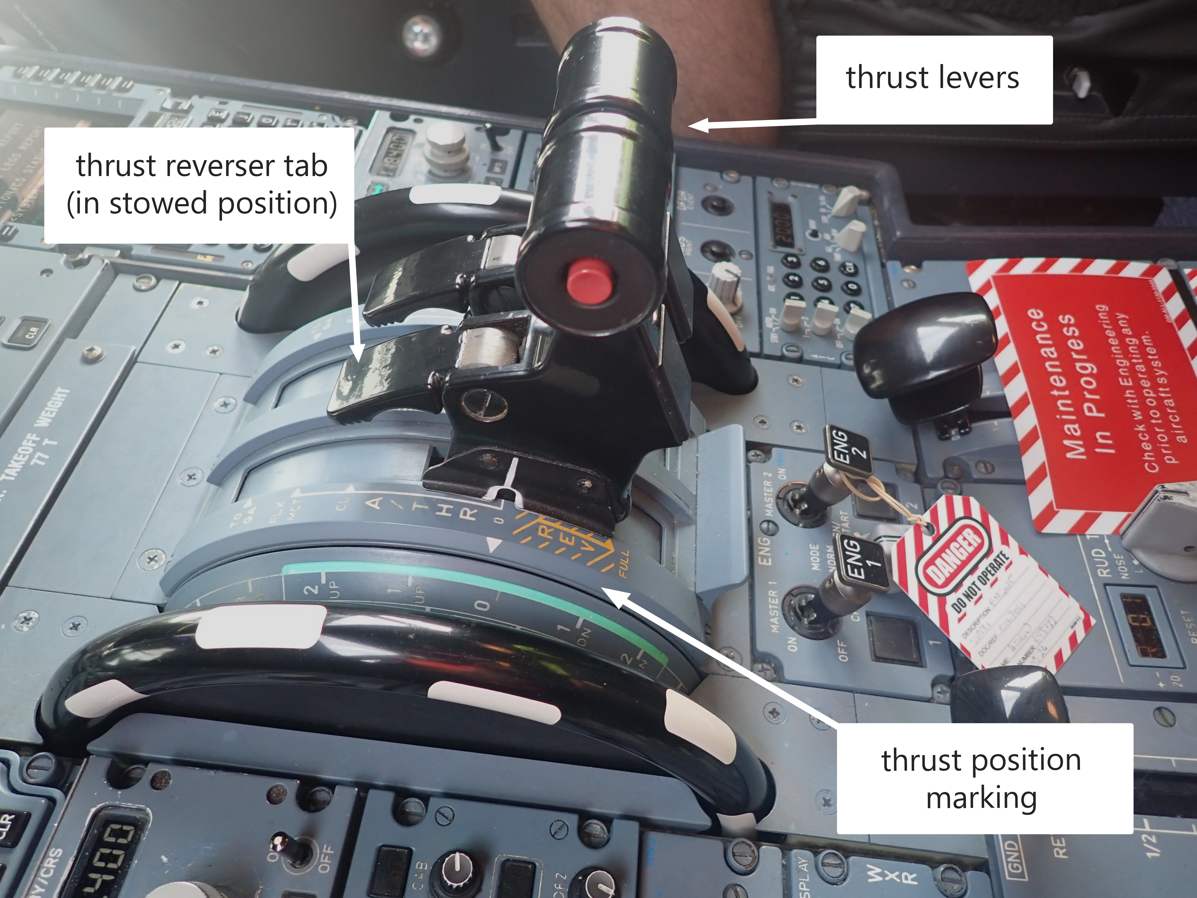
- The thrust levers can move forward to the TOGA (take-off/go around) position and back to the FWD IDLE position (depicted as 0 in Figure 5), with a detent that the pilot can feel as the lever passes each marked stage. The lever can only be moved back into reverse thrust positions if the thrust reverser tab (In the aircraft manual this is called the thrust reverser lever and is located on the front of the thrust lever (as shown in Figure 4). To avoid confusion, in this report it is referred to as thrust reverser tab) is lifted.
- There are two reverse thrust positions: REV MAX and REV IDLE. When the thrust levers are moved from reverse to the forward thrust positions, the thrust reverser tabs automatically drop into the locked position as they pass through the FWD IDLE position.
- The thrust levers have an ‘artificial feel’ unit to provide the stops, the detents and friction pressure. The force required to move a lever out of a detent is 2.5 decaNewtons (daN) (a decaNewton is 10 Newtons. This is about the same force as gravity exerts on a mass of 1 kg (9.8 N)) and the force required to move it between detents (pre-set position on the thrust lever that corresponds to a specific power setting, such as climb or idle) is about 1 daN.
- If the thrust levers are moved forward of FWD IDLE, the engine will respond and accelerate after a delay of approximately eight seconds (FADEC delay). Providing the levers are promptly pulled back to the FWD IDLE stop, the engines will go to that power setting and not spool up. FWD IDLE is the normal thrust lever position for ground taxiing while applying wheel brakes as necessary.
- Some of the operator’s pilots use a technique to walk (a technique used by pilots to move the thrust levers in a coordinated and progressive manner) the thrust levers through this movement segment. This helps minimise the force used to overcome the friction of the artificial feel unit and avoids thrust lever overshoot.
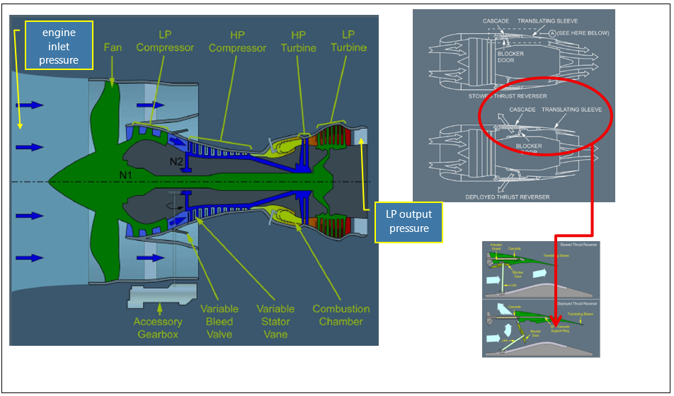
Thrust reversers
- The thrust reversers are operated by a finger-operated thrust reverser tab (see Appendix 3). This normally sits down in the horizontal position. To deploy the thrust reverser, the thrust lever must be at FWD IDLE before the thrust reverser tab is lifted to vertical. This mechanically unlocks the thrust lever and allows it to be moved into the reverse segments. The reversers are stowed by moving the thrust lever forward until the thrust reverser tabs either drop down or are encouraged to drop with slight pressure from the pilot’s fingers. When they drop, they may make a ‘clunk’ sound (see Appendix 4 for a general arrangement of the engine and the thrust reversers).
Main wheel brakes
- The main wheel brakes can be controlled automatically or manually during the landing phase. In the automatic mode, the flight crew select the braking level for the length of runway available from the options of LO, MED or MAX. This applies even braking to the main landing gear wheels to achieve the selected brake deceleration rate.
- When the pilot applies pressure to tilt the top of the rudder pedals, the wheel brakes are applied to the same side as the rudder pedal. The aeroplane can be steered left or right with differential brake application.
Nosewheel steering
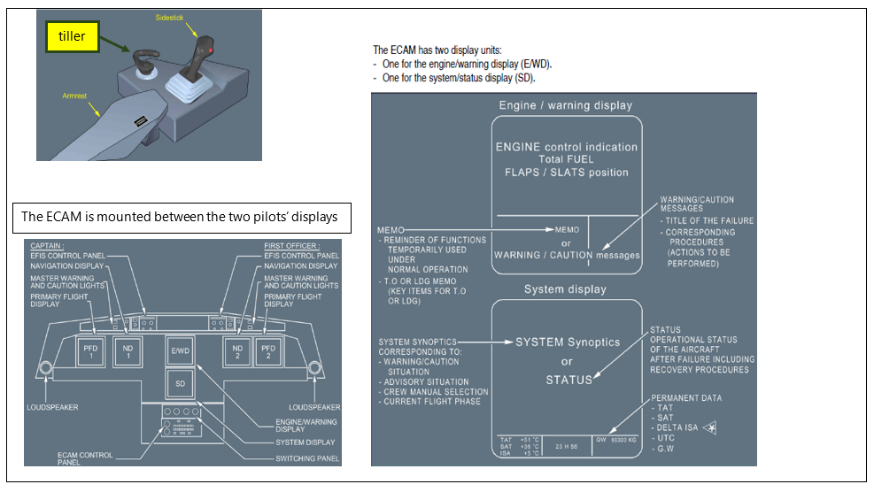
- The A320 nosewheel steering system is controlled by a brake and steering control unit (BSCU) with inputs from the rudder pedals and a small tiller device in the cockpit at both pilot positions (see Appendix 5 for an image of the tiller). The rudder pedal inputs are limited to only allow six degrees nosewheel turn angle from straight ahead with full rudder pedal deflection. Any sharper turning requirement is achieved with the tiller. Steering is hydraulically operated from the yellow hydraulic system.
- Nosewheel steering is used at low taxi speeds to manoeuvre on the ground. During take-off and landing, the BSCU gradually transfers steering authority of the nosewheel from the tiller to the rudder as the ground speed increases towards 130 kt, and back again as the speed decreases after landing.
Aerodrome information
- The aerodrome has one rapid exit to the taxiway at A4. The exit curve radius is approximately 550 metres (m), which matches the design criteria in the International Civil Aviation Organisation (ICAO) Doc 9167, Part 2 for a rapid exit for large aeroplane. It is only accessible as a rapid exit from Runway 02 direction at 1846 m from the runway end.
Recorded data
- Several sources of recorded information were obtained during this investigation.
Flight recorders
- The digital flight data recorder (DFDR) and the cockpit voice recorder (CVR) were removed from the aeroplane immediately after the accident and secured by the Commission. The recorders were taken to Canberra, where the Australian Transport Safety Bureau (ATSB) Accredited Representative assisted investigators to download the data.
Other data sources
- Christchurch International Airport Limited (CIAL) provided photographs and videos that they had taken of the accident from airport facilities, including the fire trucks, fixed cameras on buildings and an airborne video taken from a helicopter.
- Some passengers provided electronic images and recording through social media or direct to the Commission.
Site and wreckage information
- The aeroplane turned off the runway and entered rapid exit A4, then left the taxiway and crossed over the grass. The No. 2 engine impacted a movement area guidance sign (MAGS) and then the aeroplane continued in a curved path back to the runway, where it came to a stop (see Figure 6).
- Initial examination of the aeroplane found that No.2 engine had suffered significant damage to the input low-pressure fan blades and engine cowling from impact with the MAGS.
- Further examination found that hydraulic oil had been leaking from within the right-hand main landing gear stowage bay. The leak was traced to a rupture in a hydraulic pipeline that passed through the right-hand side main landing gear bay. The pipeline was a high-pressure titanium alloy pipe. The leak resulted in hydraulic oil being sprayed around the area (see Figure 7 and Figure 8).
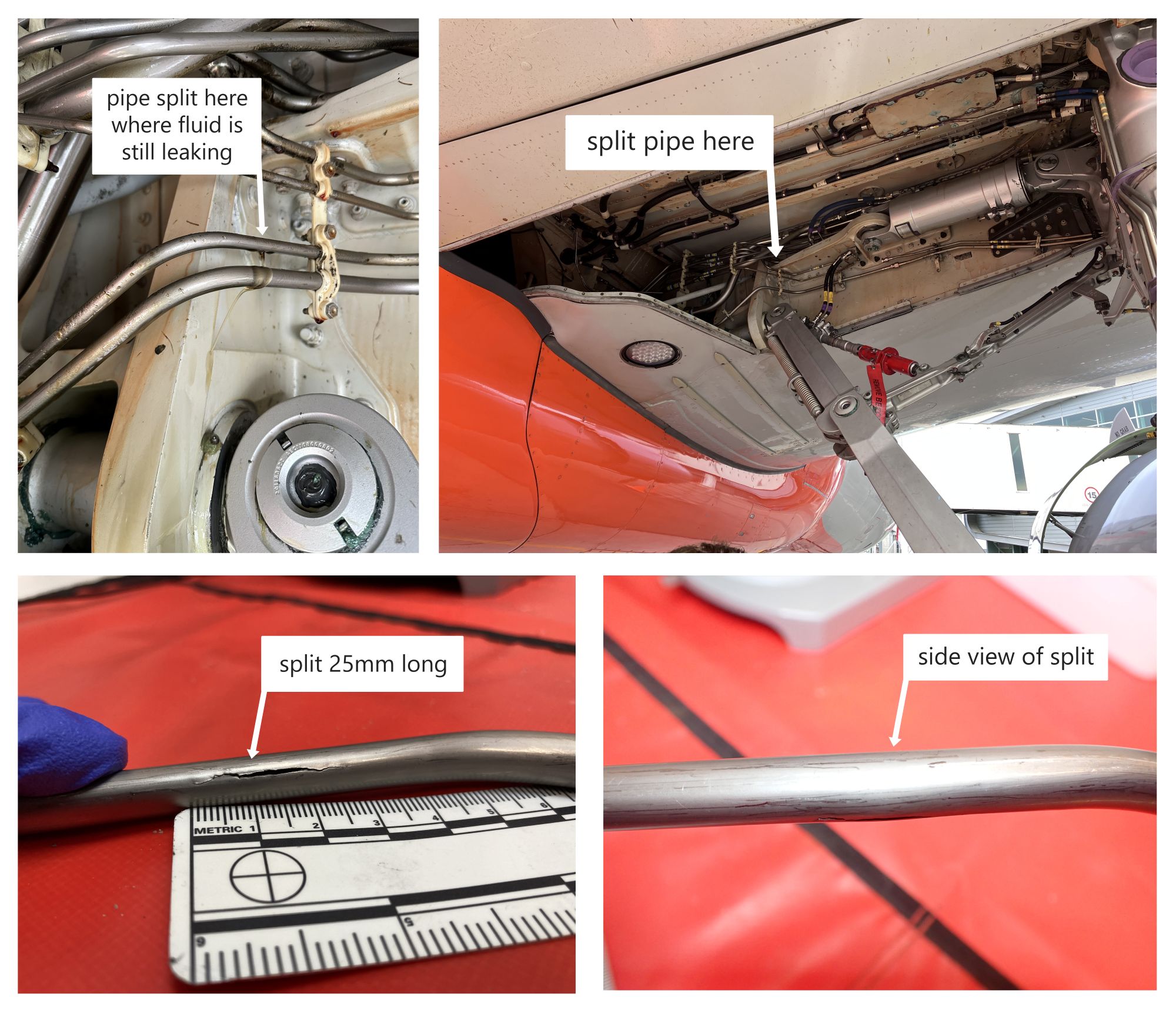
- The split was 25 millimetres (mm) long and the pipe’s (part number D2905309200020) cross section was oval in that area. Normally the pipe was round with a 9.5 mm outside diameter, but near the split the pipe diameter was 11.5 mm across the split and 8.5 mm across the perpendicular dimension.
Tests and research
- The hydraulic pipe was taken to an Airbus facility in Germany, where it was forensically examined to determine the cause of the failure. The examination was overseen by a Commission investigator.
Organisational information
- The operator, Jetstar Airways, is a wholly owned subsidiary of Qantas, based in Melbourne. Jetstar Airways has a mixed fleet of around 90 aeroplanes made up of predominantly Airbus A320 variants and the rest Boeing 787s.
- Jetstar Airways operates in New Zealand under the Trans-Tasman Mutual Recognition Act 1997 (TTMRA).
Analysis Tātaritanga
Introduction
- Data analysis of hydraulic incidents on A320 aeroplanes reported to the Civil Aviation Authority of New Zealand (CAA) over the period 2017 to 2022 showed one or two in-flight hydraulic failure occurrences per year, with a total of eight in that five-year period.
- Airbus states that, ‘Single hydraulic failures have very little effect on the handling of the aeroplane but will cause a degradation of the landing capability to CAT 3 SINGLE’ (Jetstar A320 OM18A Flight Crew Techniques Manual, PR-AEP-HYD, P 1 / 4. CAT 3 SINGLE refers to degraded aircraft automatic landing systems and equipment used in bad weather situations). The Airbus A320 aeroplane is designed to allow for redundancy if a failure occurs in one area. The degradation to landing capability was not relevant in this accident and the aeroplane remained controllable but with minor and manageable differences to some systems.
- The following section analyses the circumstances surrounding the event to identify those factors that increased the likelihood of the event occurring or increased the severity of its outcome. It also examines any safety issues that could adversely affect future operations.
What happened
- The aeroplane was in the cruise phase of the flight when the hydraulic pipe ruptured.
- After the initial response actions, the captain took over as pilot flying and worked through the implications of the hydraulic failure.
- The records show that the approach and landing were normal (see Figure 9 for the flight data track on the runway). After touchdown, the captain selected REV MAX and kept the aeroplane aligned with the centreline using rudder then brakes. As the aeroplane had slowed, the captain guided it towards the rapid exit A4 using rudder and differential braking.
- When the captain moved the thrust levers forward to stow the reversers and select FWD IDLE power, they unintentionally moved them further forward to the CLIMB position. Neither pilot noticed this incorrect selection, but the engines responded appropriately after the initial FADEC delay and accelerated the aeroplane.
- When the engines spooled up, the captain’s response was to pull both thrust levers back into REV MAX. This created asymmetric thrust, with forward thrust on the right and reverse thrust on the left, resulting in the aeroplane veering left off rapid exit A4 and onto the grass.
- Appendix 6 details the sequence of events as recorded by the DFDR.
Hydraulic pipe failure
- In October 2022, the aeroplane underwent major scheduled maintenance at the Jetstar facility in Melbourne, which took approximately four months.
- At the same time, another Jetstar A320 (VH-VQL) was undergoing a minor maintenance check. During the inspection, they found a hydraulic pipe was damaged through its free movement in a loose pipe clamp and needed to be replaced. As there were no spares readily available, the hydraulic pipe was removed from the aeroplane and installed on VH-VQL to make that aeroplane serviceable.
- A new pipe was ordered from Airbus and installed in the aeroplane before its major maintenance had been completed. The pipe was then in service in the aeroplane for 4028 flight hours and 2175 cycles before it failed 18 months later.
- The hydraulic pipe was made of titanium and about 1.8 m long. It was clamped into place and connected at each end with screwed pipe unions. It ran through the main landing gear bay on the right-hand side of the aeroplane, beside several other hydraulic pipes.
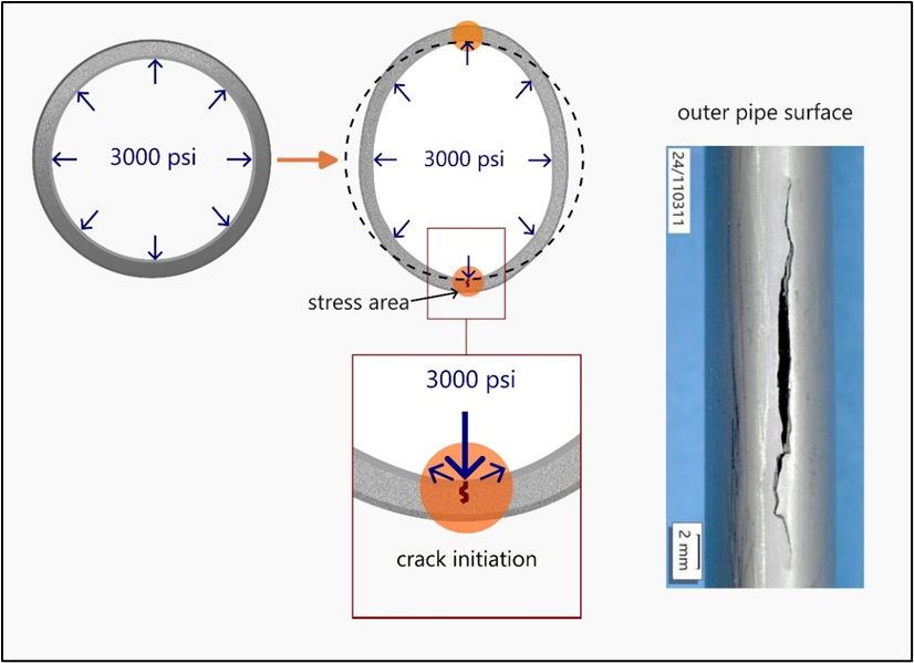
- Upon inspection after the accident, the hydraulic pipe was found to have split along a straight run between two pipe clamps. The pipe had an outside diameter of 9.5 mm and wall thickness of 0.5 mm. The hydraulic fluid was pressurised to 3000 PSI (206 Bars) so, once split, the yellow hydraulic system’s fluid contents drained very rapidly under high pressure.
- The failure had occurred in the centre of a 100 mm straight section of the 1.8 m pre-bent pipe. The pipe was oval in this area of the split rather than being round. When viewed from below, it appeared normal due to the inspection angles; the difference in width from that view angle was only 1 mm. The area was out of the way of moving parts, close to the aeroplane’s internal framework in the wing and firmly supported between two pipe clamps. The pipe had no markings on the external surface that showed it had been crushed or mechanically distorted.
- Analysis of both Airbus and Jetstar occurrence databases found no record of similar pipe failures.
- The pipe was examined by Airbus under observation by the Commission to determine if there was a material fault and why it had failed.
- The examination confirmed that the pipe material met the Airbus specification, but found that it had been physically deformed into an oval cross section in a small area by some means that could not be determined. The mode of subsequent failure was determined to have been overload on the inner pipe wall surface.
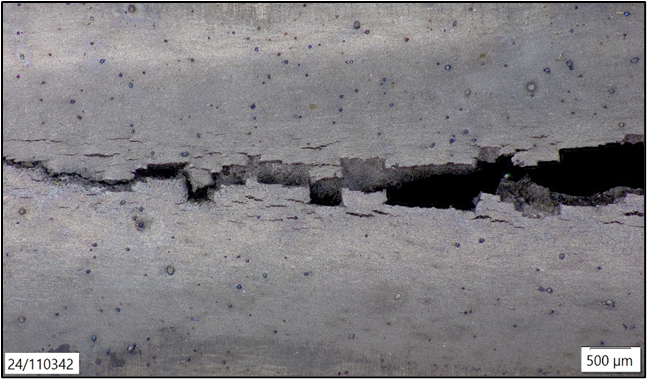
- While in operation, the internal hydraulic pressure was applied evenly to the pipe’s internal surface, as shown in Figure 10. This internal pressure would try to return the oval section to round because there would be a higher overall distribution of pressure along the internal flatter sides of the elliptical section of pipe than at the more rounded ends. This created stress areas on the inside surface of the pipe at the two sharpest bends in the oval. Fatigue (the process of damage and failure of a material due to repeated or cyclic loading of a component) due to the repetitive pressurisation and depressurisation of hydraulic fluid at each engine start-up and shut down was very likely to have exacerbated crack formation. Eventually, the inside stress led to a crack on the inside pipe surface, as shown in Figure 11. This then propagated through the pipe wall, outwards to the outside surface. The examination found that the fatigue crack had reached 95% of the pipe’s wall thickness when it failed from ductile overload. It then opened to a 25 mm-long split along the longitudinal axis of the pipe.
How was the pipe deformed?
- The life of the pipe was traced from the raw material, through its manufacturing process to delivery to the Airbus store, and then delivery to Jetstar and fitting to the aeroplane.
- The pipe started out as a section of seamless titanium pipe stock from a supplier in France that met the Airbus material specification. It was processed using cold rolling techniques, by Specitubes SAS in France into a four-metre straight section of spare pipe stock that met the hydraulic tube dimensions required by Airbus. The finished pipe was treated to relieve retained stress from the cold rolling process. This stock material of straight tube was transferred to an Airbus agent’s store in Milton Keynes, United Kingdom.
- When Airbus needed to replenish its spares holding of the hydraulic pipe, it placed an order with its supplier, GKN Aerospace in Bristol, United Kingdom. This company obtained the four-metre pipe stock and bent it to the specified shape, fitted a swaged connector (a swaged connector is a special fitting for connecting tubes. It is accomplished by forming rigid tubing outward into annular grooves within the fitting) at one end, and cut it to the specified length.
- Part of GKN Aerospace’s quality assurance testing included taking measurements at the seven bend points along the pipe length to check that the pipe’s roundness met the specification’s limits of 3% maximum ovality (maximum outside diameter – minimum outside diameter)/nominal pipe diameter x 100%). The final check was to pass a ball bearing through it with a diameter of 80% of the internal pipe diameter. Production records show that the new part met the Airbus specification and passed all GKN Aerospace quality assurance checks. It was labelled and certified as a new part, then wrapped in plastic and packaged in a rigid cardboard box. It was dispatched to the Filton Airbus warehouse in Bristol, on 22 October 2015.
- The box was received in good order at Filton, then repackaged with other spare parts and sent as a bigger package to the Airbus Fuhlsbüttel warehouse in Hamburg, Germany. It was received on 5 November 2015 with damaged packaging.
- The contents of the damaged packages were not inspected to ensure that they were still in serviceable condition. The pipe was removed and stored on a shelf, with documents and tags to show that it was serviceable, until it was required nearly seven years later.
- When Jetstar placed their order for a replacement pipe with Airbus, the pipe was picked off the shelf and sent to Melbourne with its Form 1 (standard form used to confirm an item’s conformity with an aviation part number (Authorised release certificate)) on 30 September 2022.
- When Jetstar received it, the pipe was inspected by the storeperson and its documentation checked to confirm that they matched. It passed this initial inspection and was then entered into the Jetstar parts tracking system.
- The Jetstar tracking software created a new batch number that had no correlation to the manufacturing batch number on the part’s documentation. This tracking batch number is revised each time the part is moved to another place and recorded in the Jetstar parts tracking system. When the pipe was installed, the last version of the tracking batch number and the item part number were recorded in the aeroplane work package documentation.
- When the maintenance engineer received the pipe, it was not in the same packaging as when it had left the GKN Aerospace factory. It was wrapped in plastic. They visually inspected it in accordance with the Airbus Maintenance Manual for installation of hydraulic tubes, including checks for signs of damage; that the label matched the identification marking on the tube; and that the part number matched the job task documentation. The Airbus inspection did not require any physical measurements.
- During installation, the pipe had to be marked up and cut to size to fit the other swaged fitting. The maintenance engineers held the pipe in place on the aeroplane, marked up the cutting point, and took it back to the workshop to cut and fit the swaged connector. Then they took it back to the aeroplane and fitted it into place. It was clamped in about seven places along its length and had a screwed pipe union at each end. Later the pipe would have been inspected for leaks when the hydraulics were tested.
- There were several opportunities to examine the pipe; however, the scale of the ovality or distortion would have been difficult to detect. The pipe was marked as being serviceable when it was received and visually inspected. From that point on it was considered serviceable.
- After installation, the pipe would have been inspected multiple times during maintenance checks over 4000 flight hours. It was in an area that would have also been visually checked before every flight for leaks or obvious damage over about 2000 cycles. The fact that the deformity was not noticed during almost two years in service indicates how difficult it was to detect when viewed from within the main landing gear bay.
Conclusion
- The hydraulic pipe failed as a result of overload stress on the inside surface at a deformed section of the pipe. The deformity was very likely caused when the new part’s packaging was damaged in transit from the Airbus Filton warehouse in Bristol to the Airbus Fuhlsbüttel warehouse in Hamburg. However, the part was not subsequently inspected for damage and remained labelled as a serviceable item. The damage was not detected before installation or while it was in service.
- Airbus has acknowledged the source and timing of the initial damage and recorded the case in its safety management system. Airbus informed the Commission that it will use this incident as an example in refresher training for its warehouse operators to prevent a recurrence.
Pilot’s decision to exit the runway after landing
- The operator’s Flight Crew Techniques Manual (FCTM) manual gave the flight crew two choices for taxiing with a nosewheel steering fault: use differential braking, or stop for a tow to the gate.
- The captain was concerned about the disruption they might cause to peak-time traffic if they stopped on the runway and waited for a tow. Rapid exit A4 had a shallow turn angle which they believed they could manage without nosewheel steering by using rudder and differential braking. It was also a commonly used runway exit that they were familiar with, so they planned to use rapid exit A4 for this landing. They requested a tow vehicle meet them on the taxiway once they had exited the runway.
- When they later found that the active runway had changed to Runway 20, the captain still preferred to exit the runway. Rapid exit A4 was the only shallow angled, high-speed exit taxiway at Christchurch and only useable as a rapid exit from Runway 02 direction. That meant they would need to land with a tail wind on the non-active runway.
- The flight crew rechecked the landing performance on their computer for Runway 02. Their performance calculations showed that the tail wind was manageable, and they could still decelerate to under 50 kt on the runway before rapid exit A4.
- They sought clearance from ATC to use the non-active runway. This would create a disruption to the traffic flow ATC had stacking up to use the active runway. ATC approved the request and also offered assistance to the flight crew to route them to their approach path.
Unintentional movement of thrust levers to CLIMB
- The captain reduced the reverse thrust from REV MAX to REV IDLE and then believed they had moved them further forward to FWD IDLE. They steered the aeroplane to the right towards the rapid exit A4 with brakes and rudder. Both pilots believed the thrust levers were in the FWD IDLE position and did not notice that they were in the CLIMB position.
- Eight seconds after the thrust levers were moved to the CLIMB position, at 19:45:21 (UTC time from DFDR in hours: minutes: seconds), the FADEC responded, and the engines spooled up. The aeroplane had slowed to 28 kt but then accelerated to 40 kt.
- It is likely that the flight crew did not notice the position of the thrust levers because their attention was directed outside the aeroplane and focused on steering to rapid exit A4.
- Engine parameters are displayed on a centre screen (Engine Warning Display as shown in Appendix 5), and the engine thrust gauges show the thrust lever positions as a small blue circle. The physical thrust lever position is marked on the scale beside the thrust levers.
- The captain was likely under a high cognitive load and experiencing stress. Both flight crew were likely to have experienced attention tunnelling that precluded them from perceiving wider information, including the position of the thrust levers.
- The first officer said that they did not look at the engine gauges but did check the captain’s hand positions and believed the thrust levers to have been in the correct position. After the aeroplane had stopped, the CVR recorded the flight crew reflecting on what had just happened. They could not identify the cause but were both sure the reversers had been stowed. The first officer recalled hearing the ‘click, click’ as the thrust reverser tabs dropped into the stowed position. That confirmed that the thrust levers had at least passed the FWD IDLE position.
Pilot’s response to the aeroplane’s unexpected acceleration
- The captain was aligning the aeroplane with the centreline of the rapid exit A4 to the taxiway when both pilots heard the engines spool up. The captain later said that their first thought was that the brakes had failed. It is likely that the engines spooling up startled and surprised the captain, delaying the captain’s response.
- The startle reflex is an involuntary physiological response to a sudden, intense stimulus. It can increase the heart rate, increase the tension of muscles, inhibit muscular activity and interrupt cognitive processing (Rivera, 2014) (Koch, 1999). Surprise arises from a disparity between a person’s expectations and what is perceived (Horstmann, 2006) and creates similar physiological responses to startle.
The aeroplane’s uncontrolled turn to the left
- The movement of the thrust levers into REV MAX after the engines spooled up led to an unexpected, uncontrolled yaw moment to the left. This was because the reverser on the No. 1 engine deployed, but the No. 2 engine reverser was disabled by the hydraulic failure and remained in the stowed position. The ECAM displayed an alert message, ‘ENG 2 REVERSER FAULT’, which the pilots had not expected at that time because they believed they had already stowed the reversers.
- As both engines had previously accelerated towards CLIMB power, they were developing more thrust than they would at FWD IDLE. When REV MAX was selected, both engines slowed down. The engine’s inertia prevented an immediate response to changes in thrust settings. The left engine reverser deployed, and the engine developed maximum reverse thrust while the right engine was still producing forward thrust, although it was reducing. This asymmetric thrust and pilot inputs caused the aeroplane to turn left for 60 degrees from 19:45:32.
- It is likely the captain was again startled by the aeroplane’s unexpected left turn, and that they again responded instinctively: they attempted to steer back to the taxiway with the nosewheel steering tiller, the right rudder and right brake; they moved the thrust levers forward to REV IDLE and back to REV MAX, then to FWD IDLE. They then applied both wheel brakes at 19:45:40.
- It is virtually certain that these reactions were automatic and instinctive rather than deliberate and conscious. The nosewheel steering was inoperative and the airspeed was too low for the rudder to be effective. The thrust reversers are not recommended for use at low speed unless in an emergency. They are less effective than the wheel brakes and increase the risk of engine damage from loose objects on the ground being ingested. There is also a risk with full reverse thrust at low speed that the engine might stall or the exhaust gas temperature may exceed safe limits. Moving the thrust levers to FWD IDLE and applying the wheel brakes would have been the most effective action to stop the aeroplane.
- The aeroplane continued to roll onto and across the grass, running through an illuminated ground-mounted MAGS, before moving back onto the runway. Both pilots were looking out of the cockpit at this stage but neither had any influence over the aeroplane’s directional control.
Operational guidance gap increased risk
Safety issue 1: The information provided to pilots in the aeroplane manuals for operation with a nosewheel steering fault did not include guidance on use of differential braking specifically for steering off a runway using a rapid exit. Manoeuvring an aeroplane in this condition (with nosewheel steering failure) is not a skill routinely practised by pilots, which increases their workload and the risk of an accident or incident occurring.
Operational guidance
-
This aeroplane had a failure that resulted in the loss of nosewheel steering. The aeroplane could still be steered on the ground with differential braking. Operational guidance provided for this situation in the FCTM gave the flight crew the option to use brakes to steer the aeroplane. The procedure is as follows:
NOSEWHEEL STEERING FAULT (JST A320 A321 Fleet FCTM, PR-AEP-LG P 2/4).
If the nosewheel steering (NWS) is lost for taxiing, the flight crew can steer the aircraft with differential braking technique. If the flight crew does not have experience with this technique, they should preferably request a towing to return to the gate. The flight crew can request the towing early in approach, if the failure has been triggered in flight.
- The wording in the FCTM comes from the Airbus documentation but is unmodified in the operator’s manual. Airbus has stated that the intention of this guidance was to discourage pilots from using differential braking if they do not have experience with this technique. The FCTM provided no guidance on use of differential braking specifically for steering off the runway using a rapid exit.
Motivation to avoid delays
- When interviewed by the Commission, the pilots stated that the reason for their decision to steer off the runway and use rapid exit A4 was to avoid causing unnecessary delays to other flights to or from Christchurch. If they had stopped on the runway to wait to be towed to the gate, the aerodrome could have been closed for an extended time. They had considered other options and decided this option was safe and achievable.
Training for steering with differential brakes
- In the general aviation sector, many small aeroplane types can only be steered on the ground by using differential braking, so the technique is familiar to most pilots.
- With a heavy commercial aeroplane, steering on the ground at taxi speed is normally carried out with nosewheel steering systems. Manual braking is used to control taxi speeds, but not usually for steering. Brake use has a commercial impact for airline operators, so operating procedures normally prioritise automatic braking over manual applications. Operating procedures also aim to minimise the number of brake applications.
- Normally, landing is conducted with autobrake, which applies an even brake force to each main wheel set, while steering is maintained with rudder until deceleration permits the use of nosewheel steering and the disengagement of the autobrake. Manual differential braking may be necessary in a cross-wind landing to maintain alignment with the runway centreline. However, in this accident the cross-wind was insignificant.
- Multi-pilot flight crews of large commercial jets are not provided with frequent opportunities to steer an aeroplane with differential brake applications and maintain this skill. At the time of this accident, the operator’s simulator training exercises to refresh emergency and abnormal procedures were usually concluded on landing, but before the pilots gained experience on steering with differential braking.
- It is ultimately the captain’s decision whether they stop on the runway or taxi clear when landing with an inoperative nosewheel steering system. In line with FCTM, this decision needs to consider their experience with the differential braking technique.
Thrust lever unintentional mismanagement
Safety issue 2: When moving the thrust levers from reverse to forward idle, it is possible for a pilot to unintentionally move past forward idle, resulting in an unintended increase in aeroplane engine power. An unintended increase in engine power can cause pilots to lose control of the aeroplane.
- As this investigation found, the pilots thought they had set the thrust levers to FWD IDLE but they were actually in CLIMB position. There were other indications and sensory inputs available to the pilots that could have made them aware of this unintended power setting, before the engines spooled up and they noticed the change in engine sounds.
- The operation of the thrust levers is intended to provide direct, tactile feedback to the pilot through the artificial feel unit (This is a mechanical device, forming part of the thrust lever assembly, that creates the movement feedback the pilot feels as they operate the levers. (See 2.31 for further description of this device).
- It is important that pilots understand the FADEC delay before the engines respond to a thrust lever change, to achieve better thrust lever management. When moving from reverse segments to FWD IDLE, the initial thrust lever position may overshoot but if it is promptly brought back to the idle stop, the selection will be correct. The idle stop provides a distinct, positive tactile feedback confirmation to the pilot that the thrust lever is at FWD IDLE.
- Pilots use different techniques to enhance the feedback from the artificial feel unit to ensure that they make the correct thrust lever selection. For example:
- at take-off, easing the thrust levers slightly forward to sense the power increase in both engines before selecting take-off power. This ensures even power increase and reduced risk of asymmetric thrust and a runway excursion
- walking the thrust levers through the transition from reverse to forward segments to avoid pushing too hard against the detent pressure and unintentionally pushing the levers beyond the FWD IDLE position
- moving from reverse to forward to stow the reversers, then pulling the thrust levers back to the FWD IDLE stop.
- Airbus was aware of other events where the thrust levers had been mismanaged and promoted discussion on the subject at the Airbus 29th Flight Safety Conference in Amsterdam in March 2025. They presented a paper titled ‘Thrust Lever Management at Landing’. Jetstar participants attended the conference.
- Jetstar issued an internal safety article about thrust levers and reversers. Their check and training instructors have subsequently raised the subject in pilot discussion forums to encourage sharing of experiences and generally raise their awareness about how the thrust levers and reversers operate.
- The Airbus and Jetstar manuals provide guidance on the subject of thrust lever management.
- There is one reference in the Flight Crew Operating Manual (FCOM) (JST A320 A321 Fleet FCOM PRO-NOR-JSS-F) (in the normal landing procedures about thrust levers that says:
The position of the forward and reverse thrust levers and the speed brake lever should be closely monitored by all flight crew members at all times.
- There is another reference in the SOP for landing at the end of the roll-out phase (JST A320 A321 Fleet FCOM PRO-NOR-SOP-19), where it is noted:
When deselecting the reversers, be careful not to apply forward thrust by moving the thrust levers beyond the FWD IDLE position.
- Airbus is aware of the risk that pilots may unintentionally move the thrust lever beyond FWD IDLE. Airbus has not fully explained the problem in their manuals or provided pilots with knowledge and techniques to manage the risk.
- The Commission considers that the Airbus information about the potential to mismanage thrust levers should be more prominent in documentation that Airbus provides for operators of A320 aeroplane. The manuals should also provide pilots with comprehensive information about how thrust levers physically operate, and interact with the FADEC. Pilots can then be better prepared to ensure the levers are in the selected positions, and know the consequences if they are not.
- The Commission has made a recommendation to address this safety issue.
Appendix 1. Appendix 1 A320 hydraulic architecture
Appendix 2. Christchurch aerodrome
Appendix 3. Thrust lever positions
Appendix 4. Engine arrangement and thrust reverse
Appendix 5. Aeroplane controls and ECAM
Appendix 6. Flight data record
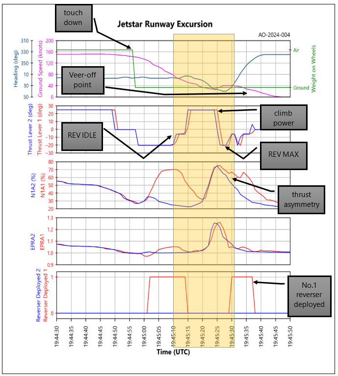
- The data from the DFDR, presented in Figure 15: DFDR data graph shows the aeroplane movements from landing to the time of the veer-off from the rapid exit A4. The highlighted band is the excursion from the taxi exit.
- The top row shows the point where the aeroplane touched down as indicated by the weight on wheels and the reducing ground speed. The heading shows that this was at 020 degrees magnetic then the aeroplane turned right onto about 040 degrees, coinciding with the turn onto A4 before it suddenly veered left towards 330 degrees.
- The second row shows the thrust lever angle in degrees of rotation. The top position is CLIMB power at (+25), and the lower at REV MAX at (-20). The lower middle position is REV IDLE at (-5) and the upper is FWD IDLE at (0).
- The third row shows the engine intake fan speed (N1) with engine No. 1 (A1) fan speed being held up to maintain the set EPR because it is operating against the backpressure of the deployed reverser. This engine is producing reverse thrust. Meanwhile, engine No. 2 fan has a lower backpressure due to the bypass air flowing straight through the engine without being diverted forward. Engine No. 2 is producing forward thrust.
- The previous peaks in this row show the normal situation after touchdown with No. 2 reverser not operational. The FADEC had compensated for the non-deployed reverser by lowering the engine power setting and only No. 1 engine fan speed had increased to generate reverse thrust, while No. 2 had remained at a suppressed idle power and lower percentage RPM. The FADEC logic is also demonstrated in the fourth row immediately below this peak by the slight increase and difference in actual engine pressure ratio (EPRA). The No. 1 engine power setting was higher than No. 2 engine while only the left thrust reverser had deployed.
- The fourth row shows the EPRA. This is the parameter that the engine FADEC controls to maintain engine power as set by the thrust levers. The ratio is calculated from the engine low-pressure turbine exhaust pressure divided by the engine inlet pressure (see Appendix 4 for the arrangement of the engine and approximate pressure sensing points). The graph shows that both engines powered up evenly about eight seconds after the thrust levers were placed in CLIMB power, then reduced to a low setting corresponding to the REV MAX power setting, immediately after the thrust levers were placed in REV MAX.
- The fifth row shows when the reversers were deployed. It takes about two seconds for the reversers to move from closed to open or the other way. The reverser tabs can only be lifted when the thrust levers are at FWD IDLE. No. 2 reverser did not deploy, but the thrust lever was in the reverse segment and both thrust levers were moved together.
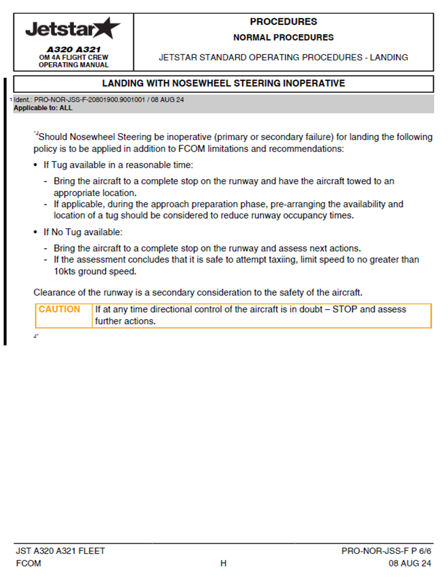
Appendix 7. Jetstar SOP revision
Jetstar issued a new landing and taxiing SOP for a nosewheel steering failure in August 2024, as a result of this accident.