A Robinson Helicopter Company R22 helicopter was being used to transfer two passengers from Karamea to a remote landing spot in Kahurangi National Park, from where the passengers were to go hunting. On the return flight to Karamea the pilot experienced a vibration and heard an associated noise. During the landing sequence at Karamea, the helicopter broke up in the air and struck the ground. The helicopter was destroyed. Pilot survived, seriously injured.
Executive summary Tuhinga whakarāpopoto
What happened
- On 2 January 2022 a Robinson Helicopter Company R22 helicopter, registration ZK-HEQ, was being used to transfer two passengers from Karamea to a remote landing spot in Kahurangi National Park, from where the passengers were to go hunting.
- Shortly after dropping off the second passenger, and on the return flight to Karamea, the pilot experienced a vibration and heard an associated noise. The pilot considered their options and elected to proceed with the flight to Karamea.
- During the landing sequence at Karamea, the helicopter broke up in the air and struck the ground. The helicopter was destroyed and the pilot, who was the sole occupant, was seriously injured.
Why it happened
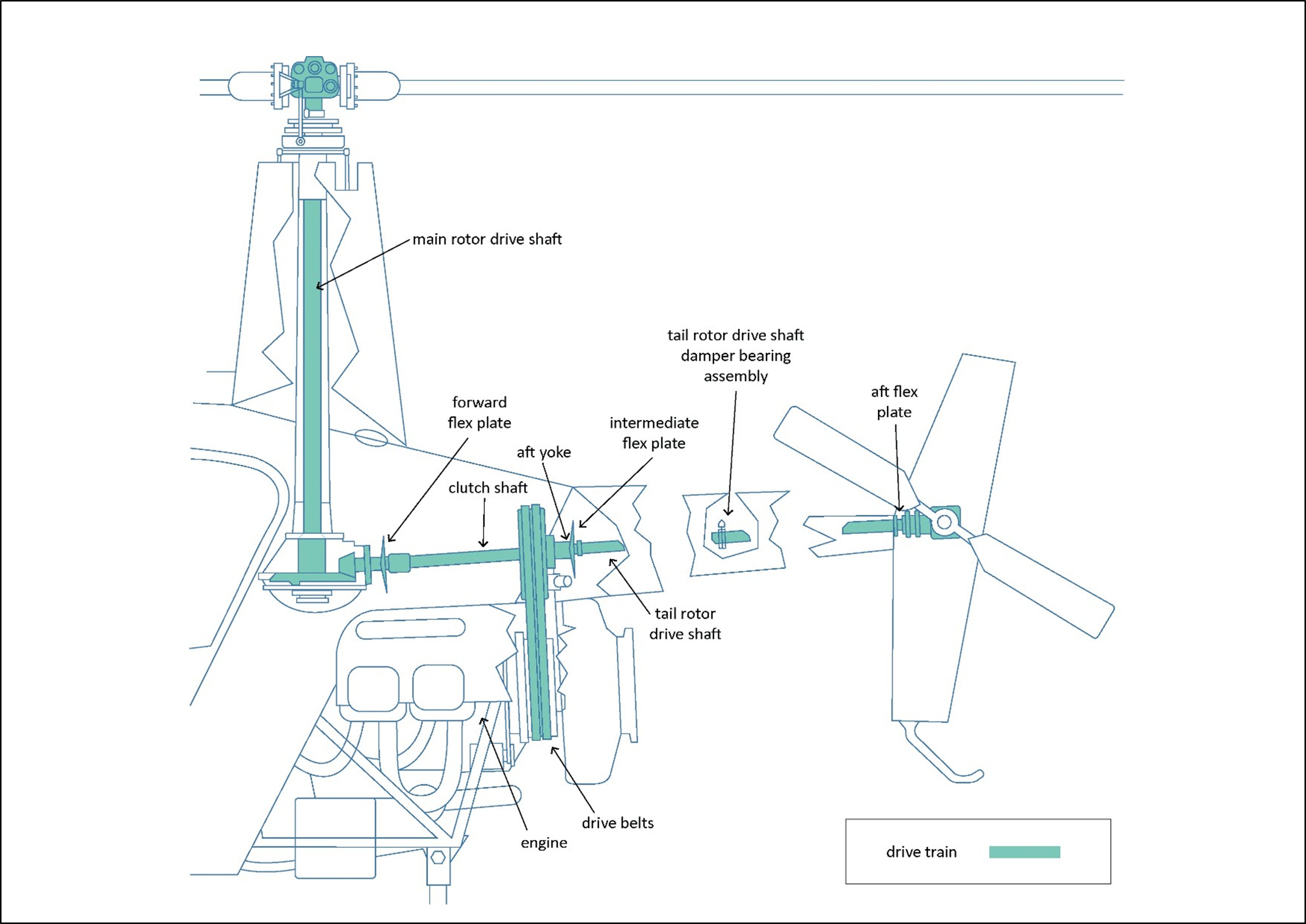
- The Transport Accident Investigation Commission (the Commission) found that the helicopter very likely experienced a rotor overspeed. This is when the drivetrain (see Figure 9) exceeds the manufacturer’s revolutions per minute speed limit.
- The rotor overspeed very likely caused the tail rotor drive shaft to deform.
- When landing, the increased power and addition of collective very likely caused the tail rotor drive shaft to deform to the extent that it contacted the tailcone’s (see Figure 7) internal structure and tail rotor control tube. This resulted in a complete loss of drive and control to the tail rotor. The pilot then lost directional control of the helicopter.
- The Commission was unable to conclusively determine when the rotor overspeed occurred. However, based on the evidence it likely occurred during take-off on the return flight to Karamea. The Commission could not rule out that another rotor overspeed could have occurred as the helicopter attempted to land at Karamea.
- The cause of the rotor overspeed was very likely a result of the helicopter being flown inadvertently outside the Robinson R22 approved rotor speed limitations.
What we can learn
- Helicopters need to be operated in accordance with the operational limitations of the Pilot’s Operating Handbook.
- Helicopter pilots need to respond quickly to the symptoms of problems and comply with the manufacturers’ instructions pertinent to the incidents and the aircraft types.
Who may benefit
- All pilots may benefit from the findings and lessons in this report.
Factual information Pārongo pono
Narrative
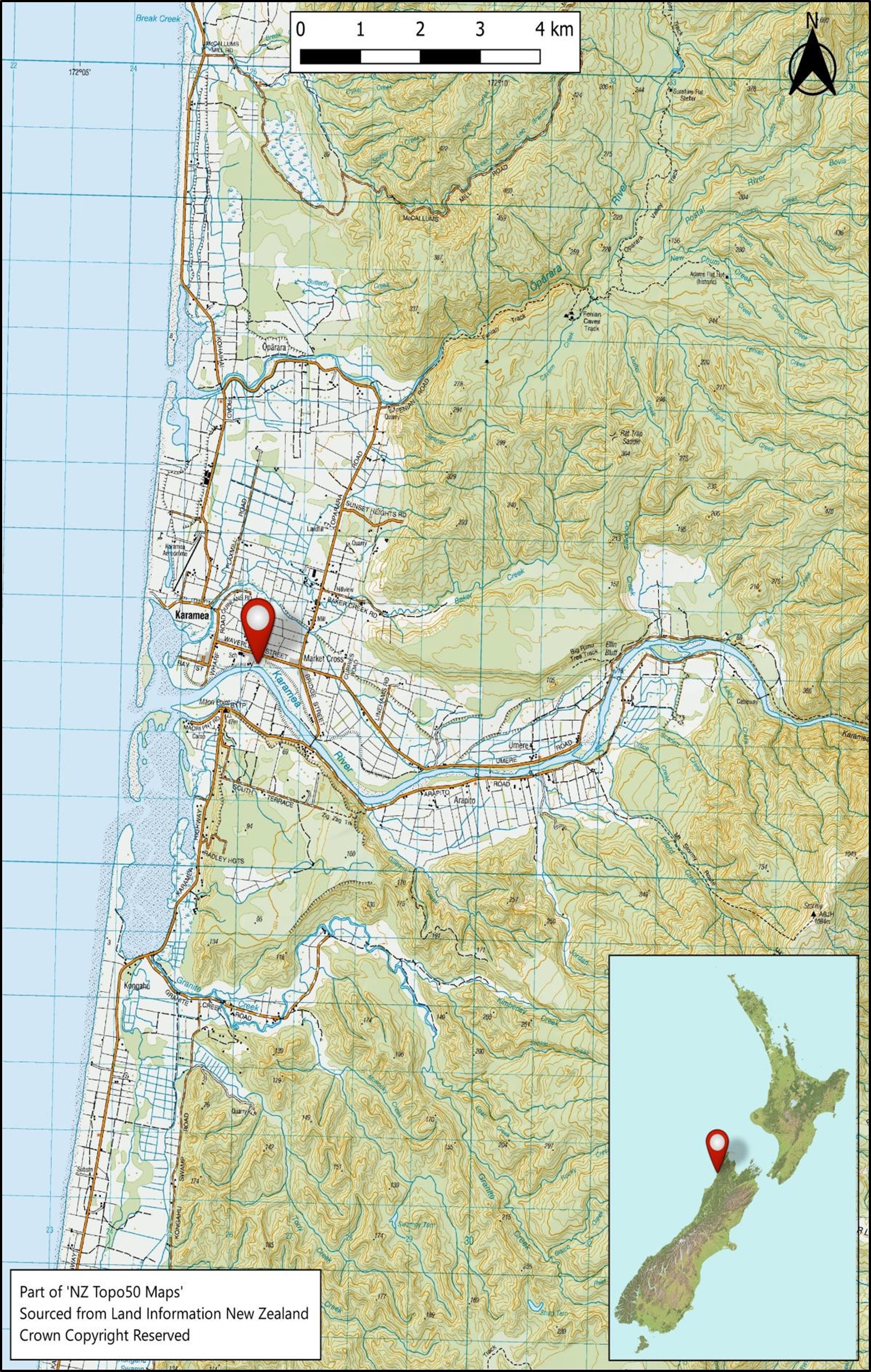
- On 2 January 2022 the pilot conducted two flights in a two-seat Robinson R22 Beta II helicopter, registration ZK-HEQ (the helicopter). The flights were conducted from the pilot’s home in Karamea, where they had an aircraft hangar.
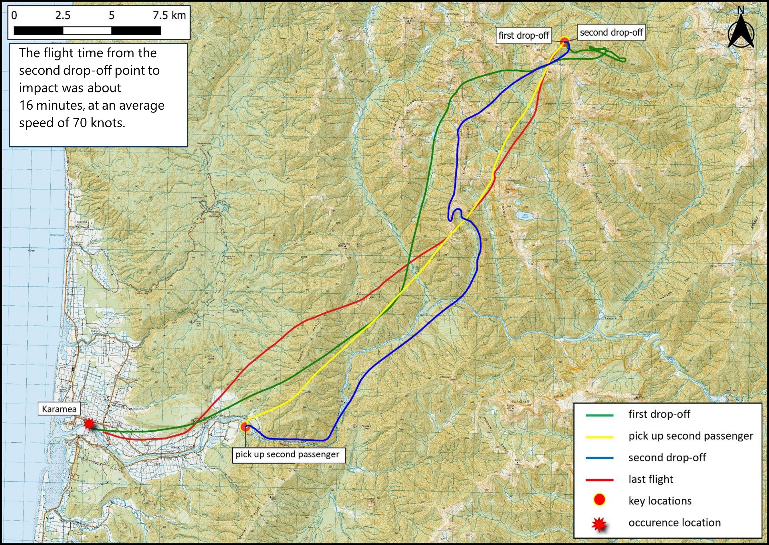
- The first flight, during which the passenger took photographs of the Karamea township, was six minutes long. The second flight, comprised of four sectors, dropped off two passengers who were to go hunting in Kahurangi National Park (see Figure 3).
- The second flight departed from the hangar at 1447 (times are in New Zealand daylight time (co-ordinated universal time +13 hours) and expressed in the 24-hour format) and the pilot flew the first passenger to a suitable drop-off point in Kahurangi National Park. The drop-off point was on a tussock ridgeline at about 4200 feet (1280 metres [m]) altitude, so the pilot assessed the engine for power before landing. The pilot kept the helicopter running while the passenger disembarked, then flew to a pick-up point in the Karamea Gorge to collect the second passenger.
- The pilot returned to the selected drop-off point and the second passenger disembarked while the helicopter remained running. At 1541 the helicopter lifted off to return to Karamea, with only the pilot on board.
- Approximately 15 seconds into the return flight, the pilot detected a vibration and heard an associated noise that they assessed as quite severe. The pilot assessed the source as at the rear of the helicopter.
- After considering their options, the pilot chose to continue the flight to Karamea, which was about 16 minutes long.
- Witnesses familiar with the local pilot and helicopter observed the helicopter flying past them, flying slower and lower than usual and on a different flight path from usual (see Figure 4). The witnesses also said the sound was distinctly different from normal; some said it sounded like the rescue helicopter that flew into Karamea occasionally (the rescue helicopter referred to by witnesses was a MBB/Kawasaki BK117-B2 that has two turboshaft engines and four main rotor blades. In contrast the Robinson R22 has a naturally aspirated piston engine and two main rotor blades).
- The pilot selected a landing spot on the north side of the Karamea River, in a grass paddock that provided easy access for emergency services.
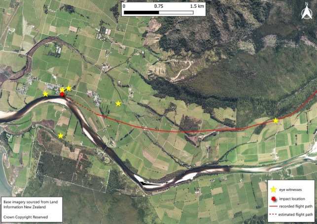
- At 1557, witnesses observed the helicopter pitching up and down abruptly and rotating to the right. During this sequence the empennage assembly (see Figure 7) and other objects were seen falling off the helicopter. The helicopter fell to the ground almost vertically in a right skid-low attitude and the engine became silent after impact.
- Witnesses on the ground responded immediately to the accident. They released the pilot from their aircraft restraint and moved them away from the helicopter. The pilot was severely injured and was air lifted to Nelson Hospital.
Personnel information
- The pilot was 71 years old and held a Commercial Pilot Licence (Helicopter). They had a total flight experience of about 8700 hours at the time of the accident.
- The pilot’s recent flight hours in a Robinson R22, between 1 October 2021 and 2 January 2022, had been approximately 72 hours.
- The pilot was the only person to fly the helicopter, apart from a number of pilots based in Nelson who flew the helicopter as part of maintenance checks.
- The pilot used the flight tracking records from Spidertracks to update their logbook. The last flight recorded in the pilot’s logbook had been on 3 November 2021.
- The pilot held a class 1 medical certificate valid to 21 February 2022.
- The pilot used hearing aids and a Bose noise-cancelling headset while flying.
- The pilot’s most recent biennial flight review and Robinson Helicopter Company safety awareness training course had been conducted on 23 September 2020. These were both current to 23 September 2022.
Aircraft information
- The Robinson R22 Beta II helicopter, serial number 4023, was constructed in February 2006 by Robinson Helicopter Company in Torrance, California, USA.
- The helicopter had been issued with a New Zealand non-terminating certificate of airworthiness in the standard category on 16 May 2008.
- The helicopter’s logbooks recorded that the helicopter and engine had been maintained in accordance with the relevant manufacturers’ maintenance programmes.
- A review of airworthiness had been carried out on 18 March 2021 with no reported defects. The next review of airworthiness was due on 18 March 2022.
- Airworthiness directives were checked against the Civil Aviation Authority of New Zealand (CAA) airworthiness directive schedule. No outstanding airworthiness directives applicable to ZK-HEQ were found.
- The helicopter’s Hobbs meter had recorded 4476.3 hours at the time of the accident.
- The last helicopter maintenance recorded had been a scheduled 50-hour inspection. It had been completed on 4 November 2021, at 4449.9 hours total time since new, and 26.4 hours before the accident flight.
- The last scheduled helicopter 100-hour inspection had been carried out in accordance with Robinson’s R22 Maintenance Manual checklist, 76.1 hours before the accident flight. The maintenance schedule encompassed a deflection check (run out) of the tail rotor drive shaft using a dial test indicator. The deflection check results recorded at that time were within limits. The next 100-hour inspection was due in 23.9 hours or before 29 September 2022, whichever occurred first.
- In March 2020 the helicopter had undergone a 2200-hour/12-year airframe inspection as per Robinson’s R22 Maintenance Manual, and records indicated that it had been flown for 281.2 hours since that time. During this maintenance visit the aircraft’s aluminium fuel tanks had been retrofitted with bladder-type fuel tanks (bladder fuel tanks were installed in accordance with Robinson R22 SB-109A to improve the fuel system’s resistance to a post-accident fuel leak. Robinson R22 bladder fuel tanks have flexible bladders in aluminium enclosures that can change shape without splitting open and spilling their flammable content).
- The pilot also used Spidertracks to record the helicopter’s flight hours in the helicopter’s technical log. Flight hours recorded by Spidertracks were transferred manually to the helicopter’s technical log; however, no flight hours had been transferred since the last 50-hour inspection on 4 November 2021.
- The Robinson R22 Beta II helicopter is fitted with a Lycoming 0360 J2A engine. The accident engine had a maximum permitted time between overhauls of 2200 hours or 12 years, whichever occurred first, in accordance with Lycoming service instruction 1009 (Lycoming, 2020). At the time of the accident the engine had exceeded the time-between-overhaul (TBO) limit by approximately 76 hours, but no engine TBO escalation programme was in place.
- The Robinson R22 Pilot’s Operating Handbook uses dates as revision numbers, identifying each revision by the date of its creation. The pilot was using a handbook that was at revision 11 May 2020. This was not the current revision status. The current revision status at the time of the accident was 17 November 2021. The handbook revision status did not contribute to the accident.
- Newer-model Robinson helicopters have high rotor revolutions per minute (RPM) audio alert systems installed to indicate to pilots when rotor RPMs are approaching 110 per cent. The accident helicopter did not have a high rotor RPM audio alert system, nor was one required.
- No maintenance defects or observations were recorded in the helicopter’s technical log before the accident flight.
Meteorological information
- A weather station located about 4 kilometres southeast of the accident site recorded the temperature at the time of the accident as 24 degrees Celsius, and a mean sea level pressure of 1023.1 hectopascals.
- Photographs taken by the first emergency responders to arrive at the accident site and a passenger at the drop-off point (see Figure 1) showed fine weather conditions with good visibility.
- The pilot advised the Transport Accident Investigation Commission (the Commission) that there had been no wind when they dropped the passengers off in Kahurangi National Park.
Weight and balance
-
At the start of the day’s flying, the helicopter contained about 60 litres of useable fuel. Commission investigators drained approximately 27 litres of fuel from the helicopter’s fuel tanks at the accident site.
- The helicopter had a recorded basic empty weight of 416.72 kilograms (kg) and a maximum certificated weight of 622 kg. Using the known weight of the pilot and the estimated weights of the equipment on board and fuel load, the helicopter was calculated to have weighed 506 kg at the time of the accident. This was 116 kg less than the maximum certified weight. The helicopter’s longitudinal and lateral centre of gravity positions were also calculated to be within limits for the flight.
Recorded data
- The helicopter did not have a flight data, voice or video recorder fitted and they were not required by Civil Aviation Rules.
- The helicopter was fitted with a global positioning system, Garmin Aera 660, in view of the pilot. This was ejected from the helicopter during the accident sequence and found damaged nearby. The recorded data was extracted by Commission investigators and used to plot and analyse the helicopter’s flight path.
- The helicopter was fitted with a Spidertracks flight tracker, which provided six-minute position updates to the operator while flights were being conducted. This data was also used by the Commission to analyse the helicopter’s flight details.
Site and wreckage information
- The accident site was the riverbank at the north side of the Karamea River, on a grass paddock about 110 m from the pilot’s hangar, the original departure location. The impact damage indicated the helicopter had fallen to the ground almost vertically in a right skid-low attitude. The helicopter was sitting upright resting on the engine, facing approximately south (see Figure 5).
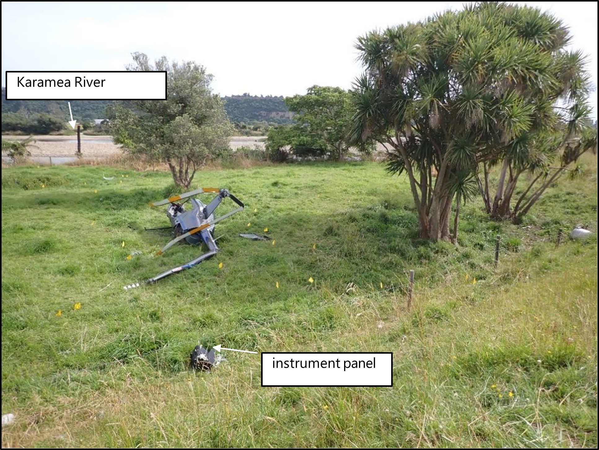
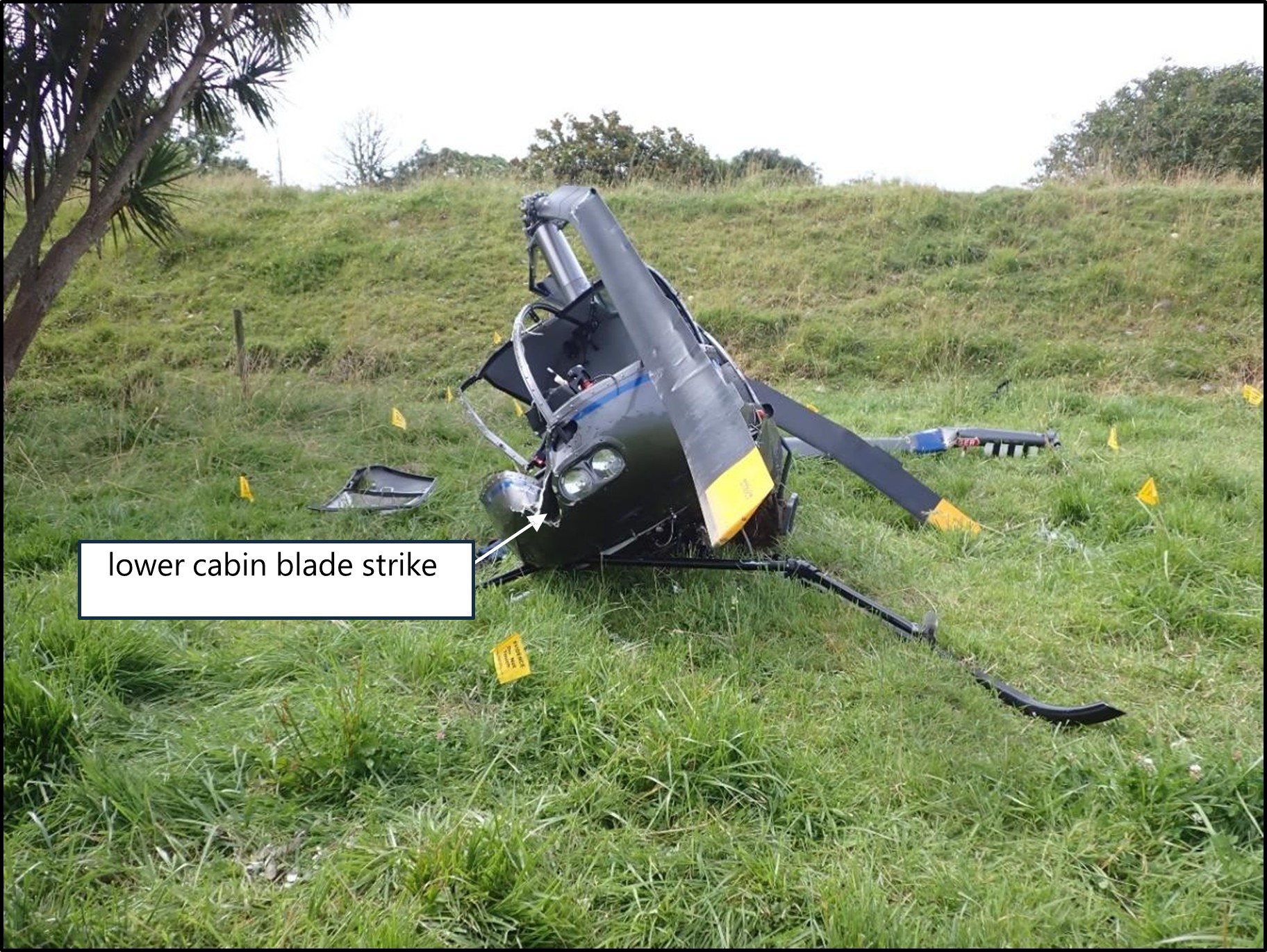
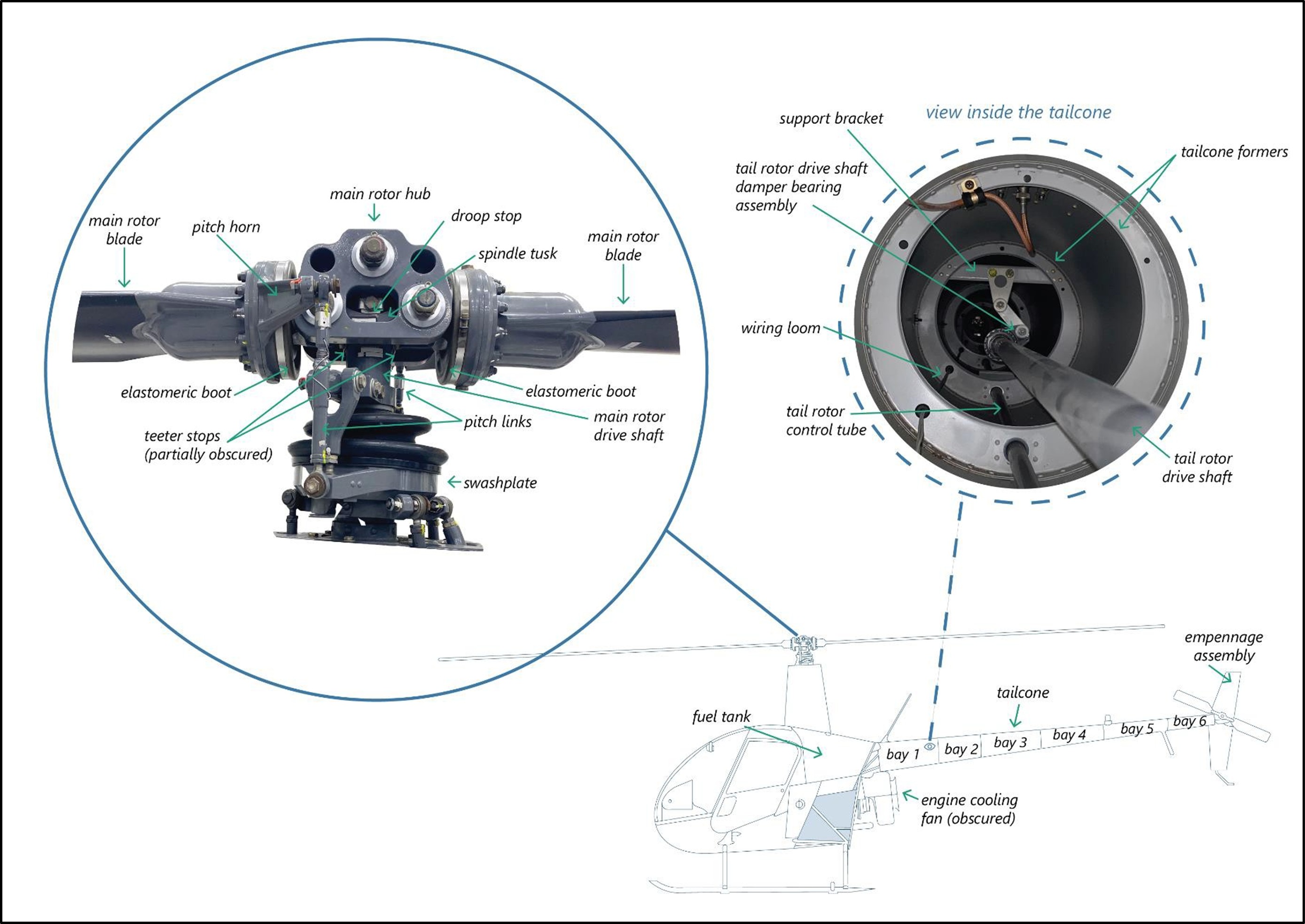
- Both main rotor blades were still attached to the main rotor hub assembly. One main rotor blade spindle tusk (which limits blade downward deflection) had sheared in overload and was found on the ground close to the helicopter. A main rotor blade had struck the lower front right of the cabin (see Figure 6). This caused the top section of the instrument panel to be projected about 9 m to the rear of the helicopter wreckage (see Figure 5). The pitch horn for this blade and both main rotor blade pitch link rod ends had broken.
- Impact damage was found on the main rotor blade teeter stops, but the damage had not progressed to the main rotor shaft.
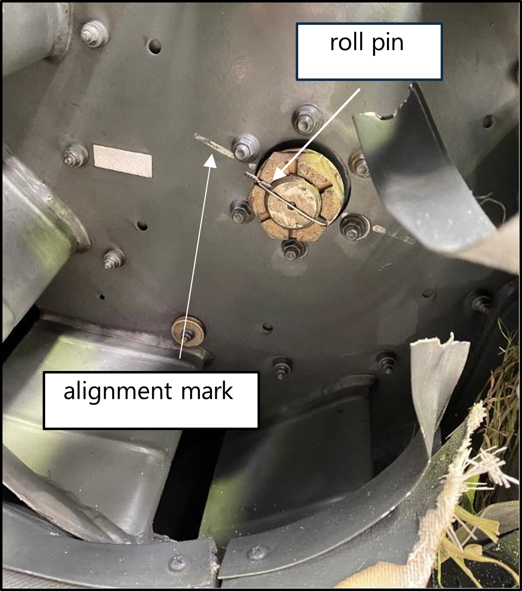
- The engine’s cooling fan (see Figure 7 and Appendix 5) was securely fitted to the tapered shaft and the alignment mark was present, showing no signs of movement between the cooling fan and the fan shaft. This ruled out the engine cooling fan being a possible source of the helicopter vibration.
- The helicopter main-rotor and tail-rotor gearboxes were equipped with electric magnetic chip detectors, used to detect metal debris in the oil. The presence of metal debris can provide an indication of wear or an early warning of impending failure. Both electric magnetic chip detectors were inspected and found to be clear of any metal debris.
- The tail rotor blades had no impact marks on the leading edges.
- The helicopter controls were found in the following positions:
- the ignition switch was in the ‘BOTH’ magneto position (on)
- the governor control switch was selected to ‘ON’
- the cyclic right trim was pulled ‘ON’
- the carburettor heat assist was unlatched and approximately 50 per cent ‘ON’
- the collective friction was selected to ‘OFF’.
- The helicopter was equipped with a Kannad 406 AF-Compact Emergency Locator Transmitter (ELT). It had separated from its mounting bracket during the accident sequence (see Figure 13). The Rescue Coordination Centre New Zealand did not receive a notification from the ELT.
- The Commission has previously made recommendations (TAIC inquiry AO-11-003, In-flight break-up ZK-HMU, Robinson R22, near Mount Aspiring, 27 April 2011) to the CAA to improve the performance of ELTs. The importance of technology in tracking and locating has been an item on the Commission’s Watchlist since 2015. These technologies improve people’s chances of surviving aircraft accidents and incidents.
Damage to the tailcone
- The empennage assembly had fractured at the tailcone aft casting and was found lying on the riverbed, 37m from the main helicopter wreckage.
- The tapered monocoque aluminium tailcone was found in two sections. The first section was found attached to the upper frame and was severed at bay two around the rivet line circumference. The second section was severely damaged at bay five (the Robinson R22 tapered monocoque tailcone is constructed in six sections (bays) joined and supported by internal formers and riveted lap joints (see Figure 7)).
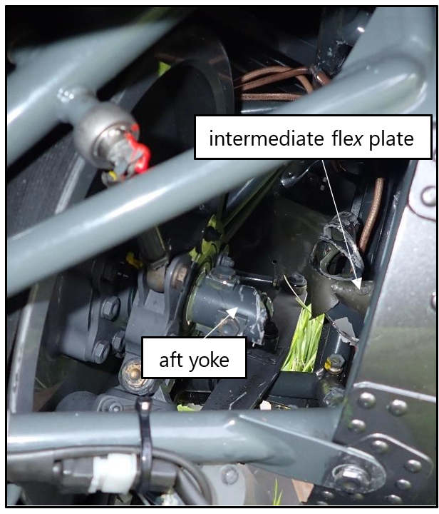
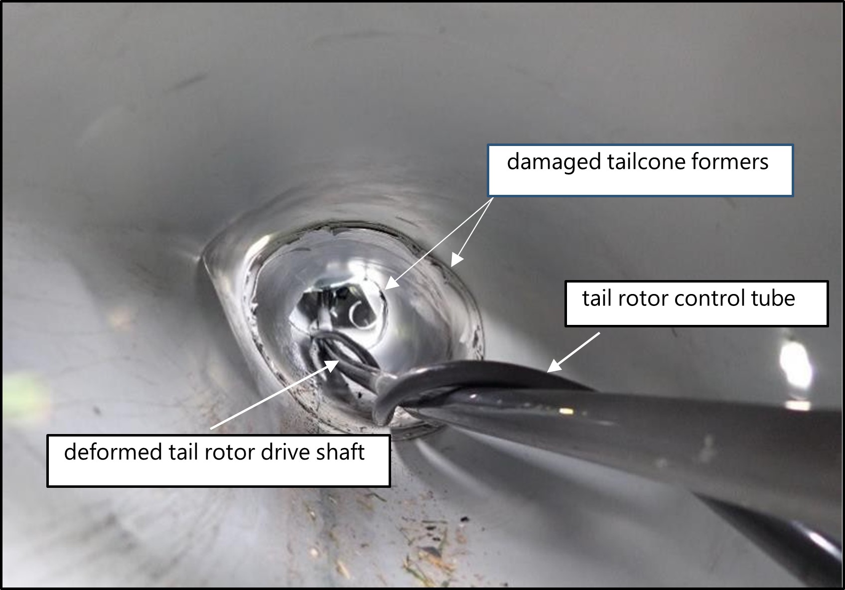
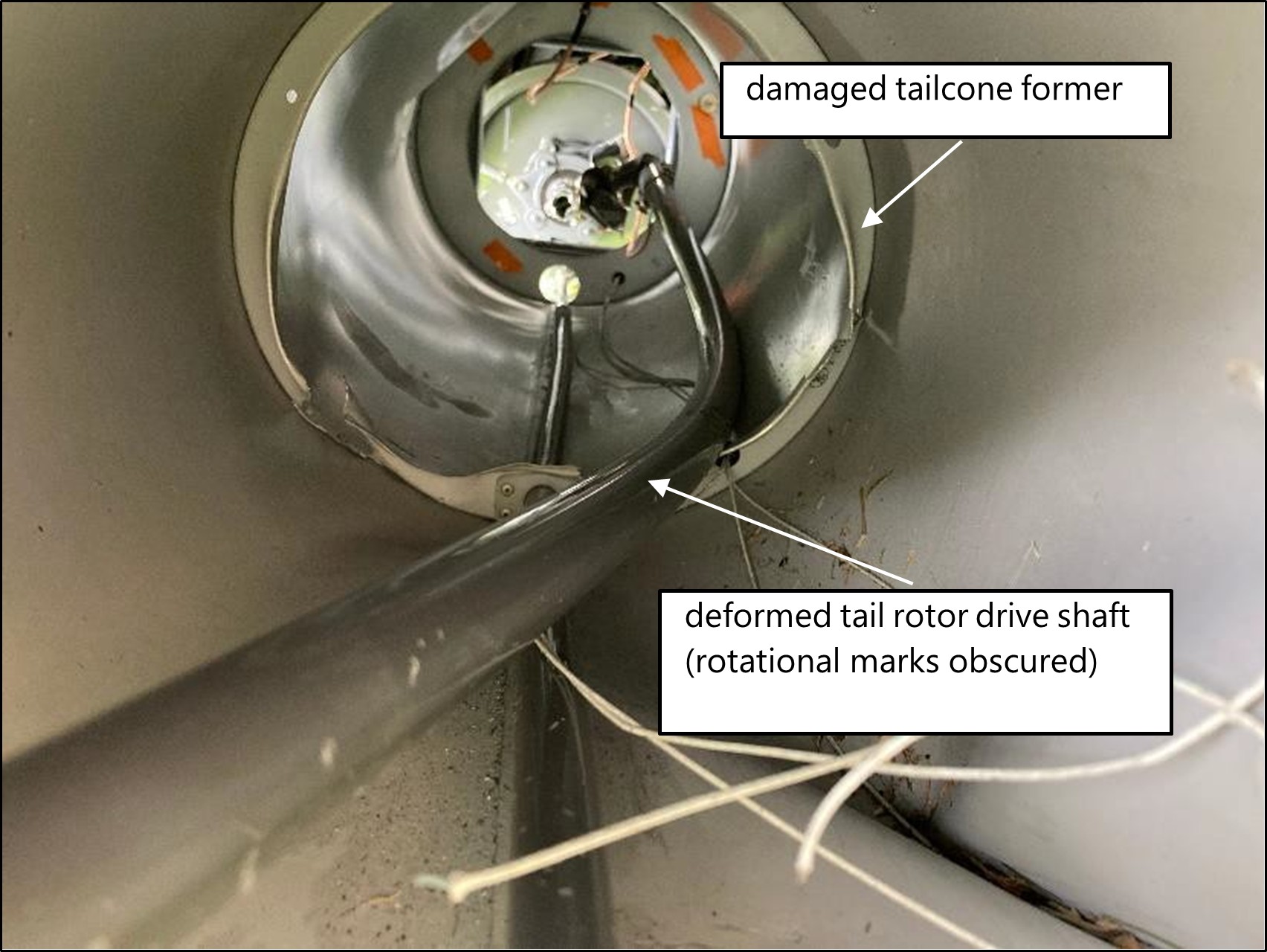
- The tailcone was damaged significantly in the accident sequence and the rotational impact from the tail rotor drive shaft caused internal damage. The tail rotor drive shaft had twisted and failed in overload forward of the damper bearing. The clutch shaft aft yoke (see Figure 9) exhibited torsional failure around the yoke’s flange (see Figure 9 and Appendix 5). The wiring loom and the tail rotor control tube had twisted around the bowed tail rotor drive shaft (see Figure 8). The tail rotor drive shaft exhibited scoring around the shaft’s circumference at intervals where it had been contacting the tailcone formers.
- The upper arm of the tail rotor drive shaft damper bearing assembly was found connected to part of its support bracket. The support bracket had separated from its mounting on the tailcone frame and exhibited a surface depression by the damper bearing. The lower arm of the damper bearing assembly had bent and fractured in overload below the upper friction washer assembly. The remainder of the damper bearing assembly affixed to the shaft, had cut through the tailcone skin from the inside.
- The tail rotor drive shaft damper bearing rotated freely, and friction was evident on both of the friction washer assemblies
- The helicopter wreckage was removed from the crash site and taken to the Commission’s technical facility in Wellington for further examination. See Appendix 1 for details of the Robinson R22 tail rotor drive shaft.
Survival aspects
- The Robinson R22 seat structure is designed to crush or collapse, absorbing vertical impact energy and preventing it being transferred to the pilot and occupant. The helicopter’s crushable seat bottom and compressible space under the seat, assisted in absorbing energy during the impact. The pilot survived the accident and resumed flying 12 months after the accident.
- Statistical trends indicate that fire is an important factor in helicopter crash survivability. The Robinson R22’s fuel system is a gravity flow system consisting of a main and auxiliary bladder fuel tank located behind the cabin. Bladder fuel tanks and rollover vent valves are intended to reduce the chance of a fuel leak in the event of an accident. The helicopter bladder fuel tanks withstood the impact and prevented a post-impact fuel leakage.
The Robinson R22 Drivetrain
- The Robinson R22 helicopter is powered by a four-cylinder Lycoming piston engine mounted facing aft (see Figure 9). A lower sheave bolted directly to the engine crankshaft transmits power to an upper sheave using two double V-belts. Located in the hub of the upper sheave is an overrunning sprag clutch.
- A clutch shaft transmits power forward to the main rotor gearbox flex plate and aft to the intermediate flex plate. The tail rotor drive shaft extends from the intermediate flex plate to the aft flex plate, transmitting power to the tail rotor gearbox. The tail rotor drive shaft comprises a long tube approximately 25.4 millimetres (1 inch) in diameter, that is located inside the tailcone. A damper bearing assembly is installed on the tail rotor drive shaft to dampen normal lateral and vertical oscillations.
Accidents related to rotor overspeeds
- A review of previous occurrences identified two other examples of Robinson R22 helicopters with similar occurrences.
- New Zealand, 11 January 1993, TAIC Inquiry 93-001 (TAIC, 1993), Robinson R22, Palmer Stream, Seaward Kaikoura Range 38 Km west-north-west of Kaikoura. While flying the helicopter between two homesteads on a large property, the helicopter heavily impacted the ground from a steep descent angle. The Commissioner’s investigators found severe damage to the internal formers of the tailcone and evidence that the tail rotor drive shaft had been gyrating within the tail cone for an extended period before impact. The investigation concluded that the probable cause for the tail rotor drive shaft to be running out of true, was either a heavy landing, tail rotor blade strike or a rotor overspeed.
- England, 13 September 2000, AAIB [Air Accidents Investigation Branch] Bulletin 3/2001 (AAIB, 2000), Robinson R22, Wycombe Airpark, Buckinghamshire. A student pilot was about to lift off on a solo flight when they experienced a violent judder. The investigation found extensive damage to the tail cone and brinelled main rotor pitch change bearings. The investigation concluded that an incorrect management of the twist grip was the most likely cause of the rotor overspeed.
Analysis Tātaritanga
Introduction
- Returning from a remote landing spot in Kahurangi National Park, the helicopter developed a vibration. The pilot decided to continue to Karamea, and the helicopter suffered an in-flight breakup during the landing sequence.
- The following sections analyse the circumstances surrounding the event to identify those factors that increased the likelihood of the event occurring or increased the severity of its outcome. One safety issue was identified with the ELT failing to operate, but it was not a contributing factor to the accident.
What happened
- The pilot was first alerted to a problem with the helicopter by a sudden vibration accompanied by a loud noise that occurred approximately 15 seconds after lift-off, after dropping off the second passenger. The pilot had not noticed this vibration on previous flights that day.
- A later examination of the helicopter revealed evidence that the rotor had very likely over sped, which had very likely distorted the tail rotor drive shaft. The eccentricity of the tail rotor drive shaft as it rotated had generated the vibration and associated noise.
- The pilot advised Commission investigators that they had attempted to diagnose the issue in flight. They had reportedly experimented with the rotor revs per minute (RPM) by moderately rolling the collective twist grip on and then off (rolling the twist grip on and off will increase and decrease the engine RPM, subsequently increasing and decreasing the rotor RPM). They advised that the variation to the rotor RPM had made no difference to the vibration intensity of the helicopter. They said the vibration and noise was synchronised at a frequency at about three cycles (beats) per second and was consistent for the remainder of the flight. The vibration was felt through the cabin floor, transferring to the tail rotor pedals, and from the back of the pilot’s seat. The pilot said no vibration was felt directly through the collective and cyclic controls.
- The pilot had considered their options while flying over rough terrain and had decided to continue to Karamea where, if required, they would have support from emergency personnel on the ground. The duration of the flight from take-off to impact was approximately 16 minutes.
- The pilot had chosen to fly at a low altitude over suitable landing sites so that they could land should the vibration become more severe. The pilot had also reduced airspeed and yawed the helicopter to the right to reduce the load on the tail rotor. The pilot had considered how to land and decided that a low-level vertical descent from hover using power was a better choice than a run-on landing or an autorotation.
- The pilot recalled that as they had attempted to land, they had slowed the helicopter from forward flight to a hover, simultaneously increasing power to maintain altitude. This had required the pilot to use left tail rotor input to counter the increased torque effect of the main rotor, to prevent the helicopter yawing around its vertical axis to the right. Adding extra torque to an already deformed tail rotor drive shaft will likely cause further deformation.
- The pilot could not remember much from then until after the accident. Witnesses saw the helicopter shaking violently from side to side and rotating. Items were flung off the helicopter as it dropped uncontrollably and struck the ground.
- An examination of the wreckage showed that the tailcone was almost severed at two points and the tail rotor drive shaft had twisted and entangled with the tail rotor control tube (see Figure 8). These were normally physically separated within the tailcone (see Figure 7) and would never have come into contact with each other during normal operation. During the accident sequence the tail rotor drive shaft deformed to the extent that it contacted the tail rotor control tube. The tail rotor drive shaft was not able to rotate after it had twisted with the tail rotor control tube, but the engine was still delivering power to it. This resulted in the forward end of the tail rotor drive shaft twisting, and torsional failure of the clutch shaft aft yoke (see Figure 9 and Appendix 5).
- When the drivetrain physically failed, the pilot lost control of the helicopter.
Evidence of a rotor overspeed
Tail rotor drive shaft
- A rotor overspeed will cause the tail rotor drive shaft to overspeed. The rotor RPM is maintained within a given operational value by the support of the helicopter’s governor and correlator (see para 3.21).
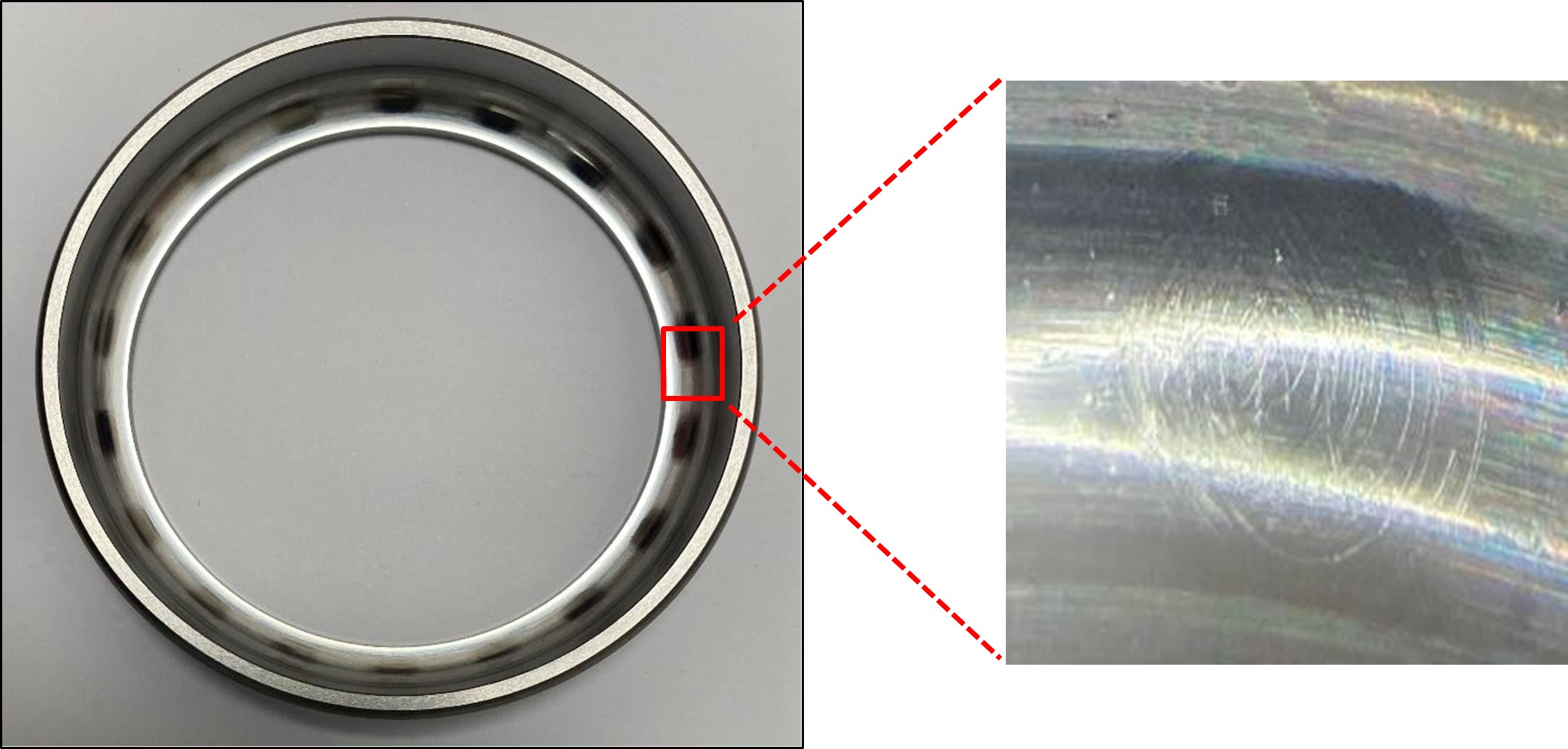
- The helicopter very likely exceeded its maximum rotor RPM limit. The rotor RPM exceedance very likely caused the tail rotor drive shaft RPM design limit also to be exceeded, resulting in elastic and subsequent plastic deformation in the tail rotor drive shaft (see Figure 10). If the deflection or deformation of the tail rotor drive shaft is within the elastic limit of the shaft’s material, it should return to its original shape once the rotor RPM is decreased. However, if the deflection or deformation of the tail rotor drive shaft exceeds the elastic limit and enters the plastic deformation range, the tail rotor drive shaft will retain its deformed shape even after the rotor RPM is decreased (see Appendix 1 and Figure 14).
- The deformed tail rotor drive shaft exhibited marks around its outer surface where it had contacted and structurally damaged the tailcone formers. The formers near the aft section of the tapered tailcone were flattened by the deformed tail rotor drive shaft gyrating in the tailcone (see Figure 8).
Main rotor pitch change bearings
- Further evidence of a rotor overspeed was confirmed after completing various rotor overspeed inspections as prescribed in the Robinson R22 Maintenance Manual. They included inspections of the main rotor pitch change bearings for rotational smoothness.
- The main rotor pitch change bearings provide angular pitch change to the main rotor blades. Each main rotor blade contains five pitch change bearings, enclosed in a housing at the blade root. The housing is filled with oil and sealed with an elastomeric boot.
- The main rotor pitch change bearings can be damaged by overload forces during a rotor overspeed. The centrifugal force pulling the main rotor blades outwards is exponential to the main rotor RPM. Therefore, overspeeding the rotor can subject the pitch change bearings to loads above their design limitations, causing permanent damage to them in the form of brinelling. Brinelling occurs when the internal raceways of a bearing have been permanently damaged by contact forces that exceed the material limit.
- When the bearings were inspected, they exhibited a noticeable notch (jerky movement) when they were rotated. This was consistent with permanent damage from overloading.
- The main rotor pitch change bearing assemblies were then disassembled by an authorised Robinson maintenance organisation under the supervision of a Commission investigator. A later examination revealed evenly spaced, polished marks and material displacement around the bearing’s race (see Figure 11), indicating bearing brinelling. The material displacement was indicative of a rotor overspeed.
- Robinson advised the Commission that there had been an increase in reports from Robinson R22 operators of premature wear and brinelling of main rotor pitch change bearings. Robinson advised, examinations of operators’ bearings revealed areas of material wear but did not exhibit the notchy characteristics and material displacement typically associated with bearings subjected to overspeed conditions (refer to Appendix 2).
How the rotor speed is controlled
- A twist grip (throttle) is located on the collective control to enable a pilot to control engine RPM manually. A manual manipulation of the twist grip is not typically required except during start-ups, shut-downs, autorotation practices and emergencies. There are three ways to manipulate the engine RPM and subsequently the rotor RPM in a Robinson R22. They comprise the correlator, the electronic governor and the pilot’s manual input.
The correlator
- The correlator controls the engine’s large power-change demands, to assist the pilot in controlling engine RPM. It provides a mechanical linkage between the collective lever and the engine’s carburettor throttle valve. The carburettor’s throttle valve is correlated to collective inputs. When the collective is raised to increase main rotor blade pitch, the carburettor’s throttle valve is opened, and conversely, as the collective is lowered, the carburettor’s throttle valve closes.
The electronic governor
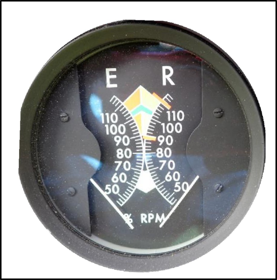
- The electronic governor senses engine RPM and rotates the twist grip accordingly to maintain RPM within the green arc range on the dual tachometer indicator (see Figure 12). The electronic governor assists in controlling the engine RPM by making minor throttle valve adjustments through rotating the twist grip on the collective control. The governor is active only above 80 per cent engine RPM and is switched ‘on’ or ‘off’ by the pilot, with the governor toggle switch located at the end of the collective lever. The governor can be overridden by the pilot gripping the twist grip too tightly or by the pilot’s manual movement of the twist grip.
- A governor light located on the instrument panel will illuminate when the governor switch is selected to ‘OFF’, to warn pilots to turn it ‘ON’, and will extinguish when the governor is selected to ‘ON’. The R22 Pilots Operating Handbook requires the governor to be ‘ON’ for normal flight. The light does not indicate a fault with the governor.
Pilot’s manual input
- In normal flight the pilot is not typically required to manipulate the twist grip. However, large and sudden flight manoeuvres or operating at high altitudes may contribute to an RPM underspeed or overspeed of the rotor, because of the slower response rate of the governor. During these conditions the pilot may be required to make manual adjustments by overriding the twist grip so that the rotor RPM is maintained within the green arc range of 101–104 per cent RPM.
- When descending in an autorotation or making a very-low-power rapid descent, the main rotor blades are driven by the aerodynamic forces resulting from the upward flow of air past the blades. A pilot’s primary means of controlling the rotor speed or RPM in this phase of flight is by using the collective lever to vary the pitch of the blades and therefore the drag. Rotor overspeeds are common during autorotation flares when the cyclic is moved aft. The pilot must counter with up collective to manage the rotor RPM. Rotor overspeeds can also occur during forward flight if the cyclic is aggressively moved aft, such as during a rapid deceleration to a stop. The electronic governor generally compensates for this, but it is possible to be aggressive enough that the electronic governor is unable to keep the rotor RPM within the green arc range of 101–104 per cent RPM.
What caused the rotor RPM to overspeed?
- The governor controller and governor motor assembly were removed and sent to Robinson for examination, under the supervision of a Commission-appointed accredited representative from the United States National Transportation Safety Board.
- An examination of the governor controller and governor motor assembly revealed that both units performed within the manufacturers’ specifications. The engine’s right magneto was also removed and examined, with no fault found.
- The pilot believed the governor had been working correctly before the accident and reported that it had been switched ‘ON’ (the governor light was extinguished) for the entire flight and had operated correctly. If the governor had been malfunctioning during the flight, the pilot would have been alerted by a change in engine and rotor noise, and erratic indications on the dual tachometer indicator. The pilot did not recall any previous governor-type problems with the helicopter.
- The investigation found no fault in the governor controller, governor motor assembly or engine magneto that would have caused RPM fluctuations. The pilot recalled that the governor had been operating correctly throughout the flight. While recognising that the governor system could not be tested in its entirety, because of the severe damage to the helicopter, it is very unlikely that a fault with the governor contributed to the rotor overspeed.
- It’s a well-known phenomenon that pilots can inhibit the governor’s input by holding the twist grip firmly (commonly known in the aviation industry as ‘strangling the throttle’). This will provide the same indications as an inoperative governor, such as engine and rotor RPM fluctuations and irregular RPM indications presented on the dual tachometer indicator.
-
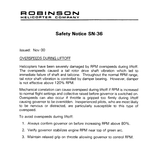
This potential mishandling technique leading to a pilot-induced overspeed had been identified to pilots in Robinson Safety Notice SN-36 (RHC, 2000) in November 2000. SN-36 outlines three precautions to avoid rotor RPM overspeeds during lift-off:
1. Always confirm governor on before increasing RPM above 80%.
2. Verify governor stabilizes engine RPM near top of green arc.
3. Maintain relaxed grip on throttle allowing governor to control RPM.
- The Commission could not rule out the possibility that the pilot’s grip had inhibited the electronic governor’s input to the pilot’s twist grip and contributed to a rotor overspeed.
- Another consideration was the possibility that the governor had not been selected to ‘ON’ before the helicopter lifted off to return to Karamea. In normal operations, the mechanical correlator will increase the engine RPM as the collective is raised, and the electronic governor will correct and finetune the engine RPM accordingly, to maintain 101–104 per cent RPM. If the electronic governor had not been selected to ‘ON’ and the collective had been raised quickly, without the pilot’s manual adjustment, both the engine and the rotor RPMs would have accelerated at rates that could have been unrecoverable. This could have exceed the Robinson R22 rotor speed limitation. The pilot reported that the governor had been selected to ‘ON’ for the entire flight, which was consistent with the procedures in the Robinson R22 Pilot’s Operating Handbook. It is therefore very likely that the governor was operating during the entire flight to Karamea.
When did the rotor RPM exceedance occur?
- The helicopter’s flight track data was analysed to consider phases of flight that could have contributed to an overspeed of the rotor RPM.
- During the flight from the first drop-off point to the Karamea Gorge to pick up the second passenger, the helicopter descended along a ridgeline at a rate of about 1950 ft (594.4 m) per minute. A rotor overspeed event was considered possible during this rapid descent profile. Robinson considers a descent rate of 1950 ft per minute to be quick for a Robinson R22 but this does not mean an overspeed occurred. Pilot technique when arresting any descent rate is critical to avoid overspeeding the rotor. Indications of a rotor overspeed would likely have been noticeable to the pilot early after this event, but the pilot did not detect that one had occurred at this time.
- After dropping off the second passenger, the helicopter lifted off and climbed about 512 ft (156 m) to clear a ridgeline. The pilot detected the vibration about 15 seconds into the return flight to Karamea. The pilot reported that the helicopter’s electronic governor was operating and the helicopter was in a stable rate of climb. As the helicopter was not in a rapid descent or an autorotation, where the main rotor blades are driven solely by the upward flow of air past the rotor, a rotor overspeed would have been unlikely to have occurred while ascending towards the ridgeline.
Pilot’s Operating Handbook advice on vibration
- The Robinson R22 Pilot’s Operating Handbook is designed as an operating guide for pilots. As the handbook is difficult to access in flight, pilots are required to be familiar with the limitations, performance, emergency procedures and operational characteristics of their helicopters.
- Robinson deems specific events as emergencies and provides instructions for those events in the emergency section of the handbook. Depending on the degree of urgency required in response to a situation, instructions such as ‘land immediately’ and ‘land as soon as practicable’ are used.
- Section 10 of the handbook contains safety tips (safety tips provide miscellaneous advice for the safe operation of a helicopter) and notices (safety notices are issued by Robinson to provide lessons from previous accidents and incidents) to help pilots operate their helicopters safely.
-
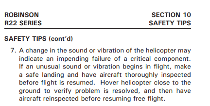
At the time of the accident, the safety tips section of the Robinson R22 Pilot’s Operating Handbook contained advice and guidance on the onset of vibrations. Safety tip 7 stated:
A change in the sound or vibration of the helicopter may indicate an impending failure of a critical component. If an unusual sound or vibration begins in flight, make a safe landing, and have aircraft thoroughly inspected before flight is resumed. Hover helicopter close to the ground to verify problem is resolved, and then have aircraft reinspected before resuming free flight.
- Safety tip 7 is not an emergency procedure, and the emergency section of the Pilot’s Operating Handbook does not contain procedures for inflight vibrations. Robinson advised the Commission that a change in sound or vibration requires the pilot to assess the situation and make their own judgement as to what will constitute a safe landing. Pilots would take factors such as vibration intensity, the pilot’s ability, environmental conditions and the available options for a clear place to land into consideration.
- The pilot explained to Commission investigators that in this occurrence they had first been alerted to a vibration and noise after dropping off the second passenger and on the return flight to Karamea, while they were flying over mountainous terrain and climbing towards a ridgeline. The pilot had attempted to diagnose the issue using the cues they had available to them at the time, and had compared the situation to an airframe vibration event they had experienced some years prior.
- The pilot had continued to evaluate their landing options during the flight to Karamea. The pilot advised the Commission investigators that because of wet surface conditions they had not wanted to conduct a run-on landing into a paddock unless the vibration became worse. They also considered a run-on landing at Karamea aerodrome, but that would have required additional flying time and power, and a flight manoeuvre that the pilot did not believe the helicopter was capable of in its current state. The pilot elected instead to fly to Karamea and execute a low-level vertical descent into a soft, grassy paddock. The pilot’s reasoning was based on their confidence that the vibration was not getting worse and that, if it were to increase during the landing sequence, medical aid would be close at hand in Karamea.
Seat belt indentations observed on helicopter’s fuel tank external surface
- The pilot had reported a regular banging noise about 15 seconds after lift-off, after dropping off the second passenger. During the examination of the wreckage, impact dents were found on the left fuel tank and engine side panel external surfaces. In addition, the left seat belt webbing damage was characteristic of the seat belt being jammed in the passenger’s door and dangling outside the helicopter during flight.
- There was a possibility that the left-hand seat belt buckle banging against the outside of the fuselage in flight matched the vibration and noise reported by the pilot. A photograph taken by the passenger at the drop-off point showed the helicopter departing but no seat belt dangling from it, so this was discounted (see Figure 1).
Summary
- Substantive evidence exists to confirm that a rotor overspeed occurred, causing the tail rotor drive shaft to deform. The Commission explored multiple possible causes of the rotor overspeed, finding that it was very likely the helicopter was being flown inadvertently outside the Robinson R22 approved rotor speed limitations. It is very unlikely the helicopter had a pre-existing mechanical fault that caused the rotor overspeed and vibration. The Commission could not rule out that the pilot’s grip on the twist grip unintentionally overrode the electronic governor which contributed to the rotor overspeed.
- The Commission was unable to conclusively determine when the rotor overspeed occurred. The pilot stated that a rotor overspeed had occurred when they applied power at about 15 to 20 feet during the accident sequence, while landing in the grass paddock at Karamea. This scenario was considered possible, but it does not explain the severe vibrations and noise experienced shortly after take-off by the pilot and the helicopter’s distinct flight profile observed by witnesses. Therefore, the Commission considered a rotor overspeed likely occurred during take-off on the flight to Karamea after dropping off the second passenger.
- When landing at Karamea the increased power and addition of collective very likely deformed the tail rotor drive shaft causing contact to the tailcone’s internal structure and tail rotor control tube, subsequently resulting in a catastrophic breakup of the helicopter.
Emergency locator transmitter (ELT)
Safety issue: Hook and loop retaining straps, commonly known as Velcro, are relied upon by many ELT installations to secure the ELTs to the mounting brackets on aircraft airframes. However, there is a risk of these hook and loop retaining straps losing their designed capability to retain ELTs during accidents, thereby rendering the ELTs ineffective and causing delays in life-saving search and rescue operations.
- In the event of an aircraft accident, the primary function of an ELT is to automatically activate and transmit an encoded signal to the Cospas-Sarsat satellite network and subsequently a notification to the Rescue Coordination Centre New Zealand.
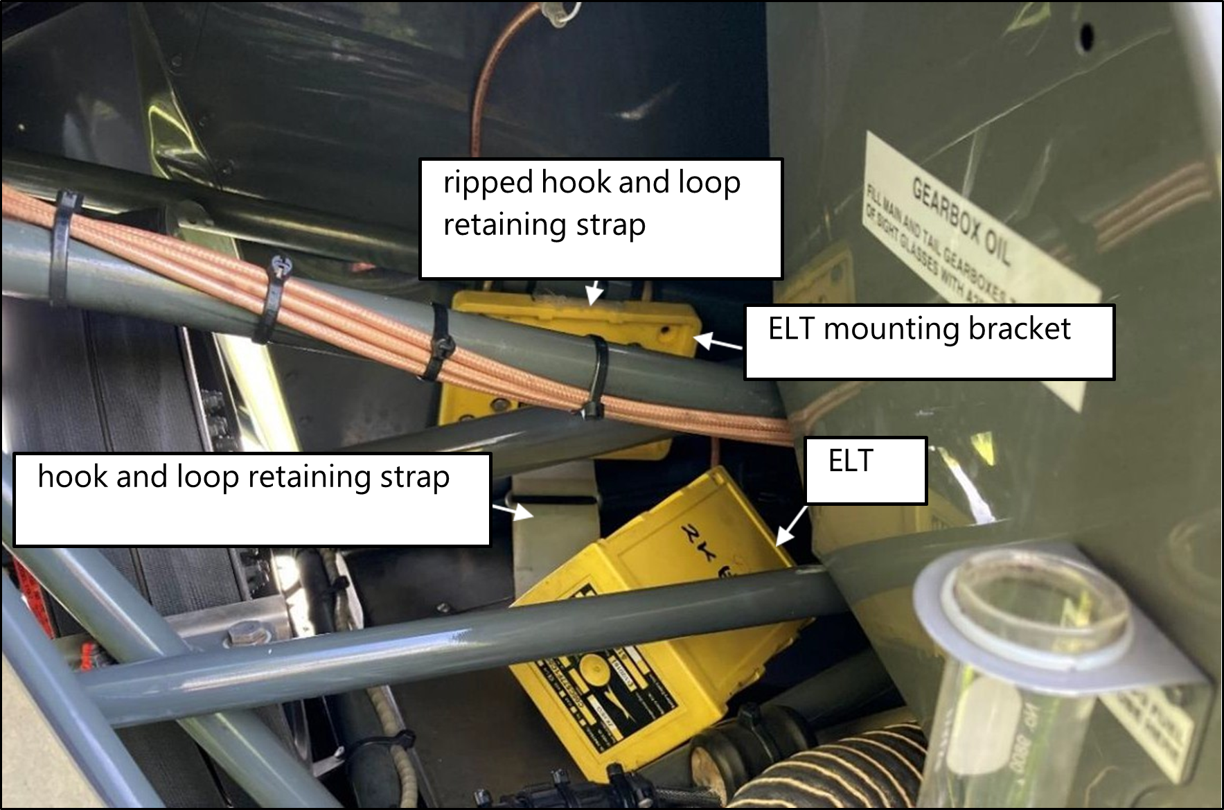
The helicopter was equipped with a Kannad 406 AF-Compact ELT, installed on the helicopter’s upper frame assembly and adjacent to the helicopter’s drivetrain. - The ELT was mounted with a hook and loop retaining strap. The strap ripped during the helicopter’s impact with the ground, allowing the ELT to separate from its mounting bracket (see Figure 13). The ELT switch was in the arm position. The ELT failed to activate in this accident. It is virtually certain that the activation force was dampened when the ELT separated from its mounting bracket.
- The ELT was found free from its mounting bracket and retaining strap but still connected to the antenna cable. The wiring for the remote switch had been pulled out of the connector, preventing the ELT being manually activated from inside the cabin.
- The Commission assessed whether the ELT had separated from its mounting bracket during the flight and whether that had caused a noticeable noise and vibration. If the ELT had been separated from its mounting bracket during flight it could have rattled on the
horizontal firewall or contacted the forward yoke. No impact marks were found on the ELT’s external case nor did the ELT activate during the flight. It is therefore virtually certain that the ELT separated from its mounting bracket during the accident impact and not during the flight. - The estimated g-force of the helicopter’s impact with the ground was within the ELT’s activation threshold. The ELT was tested at a Kannad service facility. It was found to be serviceable and passed the manufacturer’s test performance specifications, including the g-switch activation test. The ELT memory had no recorded transmitted 406-megahertz bursts. It was virtually certain that the ELT was not activated in this accident when the circumstances indicated it should have been.
- The ELT’s separation from its mounting bracket was largely consistent with the reports of an ELT hook and loop retaining strap failure described in Robinson Service Letter SL-92 (on 3 March 2022 the Federal Aviation Administration also issued Special Airworthiness Information Bulletin SAIB AIR-22-03, applicable to owners and operators of Robinson helicopter models equipped with Kannad ELTs) (RHC, 2021), issued to owners, operators and maintenance personnel on 30 June 2021. Service Letter SL-92 necessitates periodic inspections to:
- verify the ELT is properly seated in the mounting bracket
- verify the hook and loop retaining strap has no slack or deterioration
- replace the hook and loop retaining strap if damaged or every 12 years
- ensure a secondary strap is installed.
- Compliance with Service Letter SL-92 was not recorded in the aircraft’s logbook and secondary ELT strap had not been fitted to the ELT.
- Civil Aviation Rules required the accident helicopter to be fitted with an ELT compliant with Technical Standard Order TSO-C126. The ELT’s maintenance programme required the ELT to be tested and inspected in accordance with Civil Aviation Rules Part 43, Appendix F and the manufacturer’s instructions, at intervals of 100 flight hours or 12 months, whichever occurred first. The most recent ELT inspection carried out in accordance with Civil Aviation Rules Part 43, Appendix F had been on 29 September 2021, about three months before the accident.
- There are documented accidents in which the hook and loop retaining straps have failed (see FAA AC 91-44A para 7.6.1). These failures led to the ejection of the ELTs from their mounting brackets. Consequently, the antenna connections severed and the activation g-force was dampened. Such failures have rendered ELTs ineffective and delayed search and rescue operations.
- On 23 May 2012 the Federal Aviation Administration (FAA) issued a special airworthiness information bulletin, HQ-12-32, recommending that ELT manufacturers revise the ELTs’ Instructions for Continued Airworthiness to address the risk of a hook and loop retaining strap failure. ELT manufacturers then issued detailed guidance on securing their ELTs and provided methods for inspecting and determining the appropriate tensions of hook and loop retaining straps during installation and removal.
- On 26 November 2012 the FAA updated Technical Standard Order TSO-C126a to TSO-C126b, which stated that ‘the use of hook and loop fasteners is not an acceptable means of attachment’ for automatic fixed and automatic portable ELTs. However, this revised Technical Standard Order is not retroactive, so hook and loop retaining straps will continue to be used in existing installations for the foreseeable future.
- The retention characteristics of the hook and loop retaining strap degrade over time because of wear and environmental degradation from vibration, temperature and/or contamination. Inconsistent installation practices and non-prescriptive inspection limits can lead to the hook and loop retaining strap not having the necessary tension and durability to perform its intended function. Additionally, some manufacturers do not impose mandatory replacement intervals for hook and loop retaining straps.
- The hook and loop retaining strap remains compliant for ELT installations, but it comes with a consequent risk that the ELT will fail to operate in an accident.
- The Commission is concerned about the number of times ELTs have failed to operate correctly and has therefore made a recommendation to address this safety issue.
Other observations
- The continued airworthiness and management of an aircraft is the owner’s or operator’s responsibility. Managing the continuing airworthiness of an aircraft is a complex function and requires a thorough understanding of the Civil Aviation Rules and the aircraft’s maintenance programme.
- The helicopter’s records indicated that the engine had exceeded Lycoming Engines’ time-between-overhaul limit by about 76 hours. Engine manufacturers establish and prescribe recommended time-in-service intervals for safe and reliable engine operations. To operate this engine beyond its manufacturer’s recommended time between overhauls, a time-between-overhaul escalation programme and procedure accepted by the CAA would have been required. The records did not identify any additional escalation programme to extend the engine past Lycoming Engines’ recommended time between overhaul.
- The engine’s time-between-overhaul exceedance did not contribute to the accident.
- It is an owner’s or operator’s responsibility to maintain records of time in service for an airframe, an engine and life-limited components. An accurate and timely recording of flight time using a method pertinent to the aircraft’s manual and/or Civil Aviation Rules mitigates maintenance overruns. It ensures that all maintenance is conducted within the scheduled intervals for continued airworthiness.
- A pilot’s logbook is a record of the pilot’s cumulative flying hours, training and overall experience. Pilots are required by Civil Aviation Rules Part 61.29 to keep their logbooks up to date, as this helps to minimise clerical errors and ensures that the pilots’ currency and compliance with the Civil Aviation Rules is documented.
- In this case the pilot had been relying on the flight tracking data to retrospectively complete their personal logbook and the technical log for the helicopter. Neither were current at the time of the accident but this did not contribute to the accident.
Appendix 1. R22 tail rotor drive shaft
Tail rotor drive shaft standing wave patterns
- The tail rotor drive shaft has a lightly loaded damper bearing, therefore is unsupported by fixed bearings for its length of approximately 3.58 m (141 inches). Normally the shaft rotates on its centre line, but under certain circumstances, such as being allowed to spin faster than its physical limit or being subject to a greater torque loading than designed, it can deflect. If deflection exceeds the elastic deformation47 range of the shaft material, the deflection becomes permanent. It is checked during maintenance checks to ensure it is still within tolerance from the centre line, so an out-of-limits shaft can be detected and replaced before it causes damage.
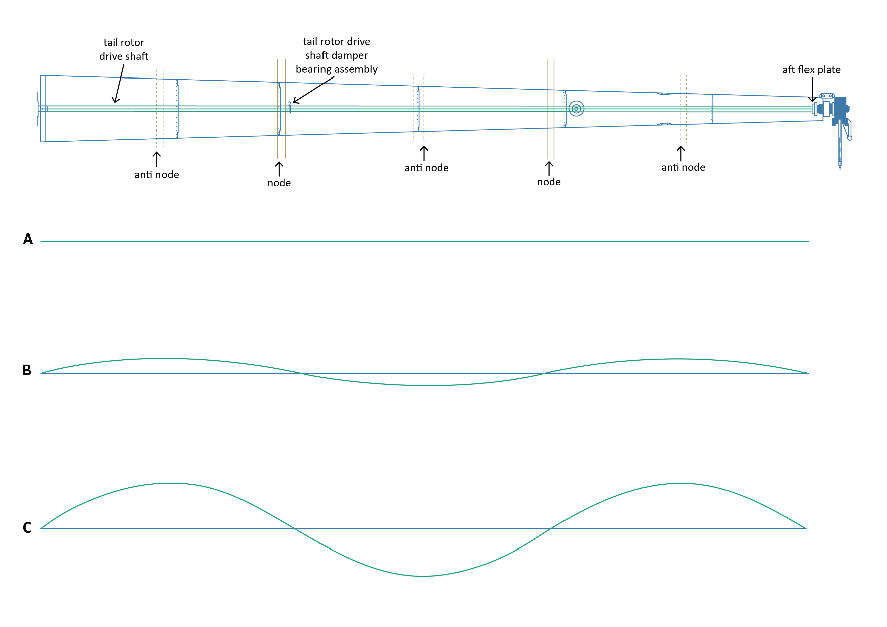
- As the tail rotor drive shaft rotational speed is increased, it will reach a point where it starts to oscillate (see Figure 14). A damper bearing mounted flexibly at a position near one third the length back from the intermediate flex plate, is designed to dampen the onset of tail rotor drive shaft oscillations. Should the rotor RPM exceed approximately 120 per cent (where 101–104 per cent is normal), the tail rotor drive shaft damper bearing is not effective. If the rotor RPM reaches a speed of approximately 132 per cent, the tail rotor drive shaft will deflect forming a standing sine wave shape (see Figure 14). As the rotational shaft speed increases, so will the amplitude of the peaks. At some point, the tail rotor drive shaft elastic deformation range will be exceeded, resulting in plastic deformation48 to the shaft.
- A representative example of the tail rotor drive shaft oscillating patterns during various speeds is shown in Figure 14. The pattern has been provided by Robinson to show the effect of excess tail rotor drive shaft rotational speed, but the wave patterns are exaggerated for clarity.
- Row ‘A’ demonstrates the shaft pattern for normal operational speeds between 101 per cent and 104 per cent of the rotor RPM.
- Row ‘B’ shows the formation of a standing wave pattern as the rotor speed accelerates to 132 per cent. An increase in the tail rotor drive shaft rotational speed will increase the amplitude of the standing wave.
- Row ‘C’ shows when the amplitude has increased to a critical level, resulting in plastic deformation to the tail rotor drive shaft.
- Any movement of the tail rotor drive shaft away from its normal centreline will result in vibration and a pulling force from the two flex plates towards the centre of the tail rotor drive shaft.
(Credit: TAIC, in liaison with Robinson Helicopter Company design engineers)
Appendix 3. R22 Pilot’s Operating Handbook – safety notices and tips
Robinson Helicopter Company Safety Notice SN-36
Robinson R22 Series safety tip 7
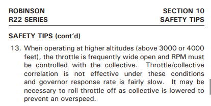
Robinson R22 Series safety tip 13
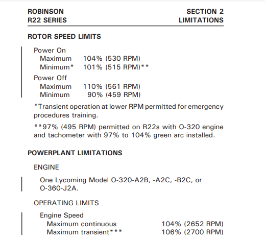
Appendix 4. R22 Pilot’s Operating Handbook - Section 2, Limitations
Rotor and engine speeds
Appendix 5. Wreckage examination