On 19 September 2023, an air ambulance helicopter was dispatched from Hamilton Airport to recover a trauma patient on Mount Pirongia. On board the Kawasaki BK117 B-2 helicopter were a pilot, a crew member and a paramedic. While descending on the windward side of a ridge line to recover the patient by winch extraction, the helicopter rapidly and unexpectedly dropped in height. The helicopter impacted the terrain on a west-facing escarpment covered by dense native forest. The helicopter was severely damaged. The pilot, crew member and paramedic escaped without injury.
Executive summary Tuhinga whakarāpopoto
What happened
- On 19 September 2023, an air ambulance helicopter was dispatched from Hamilton Airport to recover a trauma patient on Mount Pirongia (Waikato region). On board the Kawasaki BK117 B-2 helicopter were a pilot, a crew member (the crew member was a hoist (winch) operator) and a paramedic.
- While descending on the windward side of a ridge line to recover the patient by winch extraction, the helicopter rapidly and unexpectedly dropped in height. The helicopter impacted the terrain on a west-facing escarpment covered by dense native forest.
- The helicopter was severely damaged. The pilot, crew member and paramedic escaped without injury.
Why it happened
- It is virtually certain that the helicopter entered Vortex Ring State (VRS) while descending on the windward side of a ridge line to recover the patient. VRS is a hazardous aerodynamic phenomenon that a helicopter can encounter during the descent and landing phases of flight and during manoeuvres at low forward speed. The onset of VRS can lead to a rapid loss of main rotor lift and then to a sudden increase in the helicopter’s rate of descent.
- The helicopter's trajectory, particularly its descent rate and forward speed, combined with its pitch attitude and the presence of orographic uplift across the ridge, was conducive to the onset of VRS.
- While on final approach, the pilot assumed that they could continue the approach to the winch site in level flight. During this critical phase of flight, the pilot’s visual attention was primarily focused outside the cockpit on the patient’s location. As a result of a reduced instrument scan, indications that the helicopter’s forward speed and descent rate were conducive to VRS were not immediately recognised.
- The helicopter’s height above ground level (AGL) during the onset of VRS provided the pilot with insufficient time to perform an effective recovery.
- During helicopter flight training, pilots receive generic tuition on VRS. The helicopter’s Flight Manual did not contain the information necessary for the pilot to identify the flight conditions and parameters for the helicopter type that were conducive to VRS.
What we can learn
- The omission of guidance by the helicopter manufacturer on the avoidance and recovery from VRS poses a significant risk to operators.
- It is critical that helicopter pilots understand what VRS is and how they can avoid entering it.
- Flying in mountainous terrain presents helicopter pilots with multiple challenges, including misinterpreting the air environment in which they are flying. Pilots need to use all available sources of information to ensure they are not subject to visual illusions that might lead them to misjudge their forward speed and rate of descent, particularly when operating close to the ground.
- Standard operating procedures help ensure that an aircraft is operated and flown in as safe a manner as possible. Modifying these procedures can increase the risk of an adverse outcome.
Who may benefit
- All helicopter pilots, operators, flight schools and manufacturers may benefit from the findings and recommendations in this report.
Factual information Pārongo pono
Narrative
- ZK-HHJ (the helicopter) was a Kawasaki BK117 B-2 air ambulance helicopter operated by Search and Rescue Services Limited (the operator). On Tuesday 19 September 2023, the day-shift crew (the crew) were on standby from about 0700 (times are in New Zealand Standard Time and expressed in 24-hour format). The crew consisted of one pilot, a crew member and a paramedic.
- The crew’s first assigned job was an inter-hospital transfer from Taumarunui Hospital to Waikato Hospital. The flight departed from Hamilton Airport at 1017, returning at 1312, and was uneventful. The second assigned job was to recover a trauma patient, an injured tramper, from near Te Awamutu.
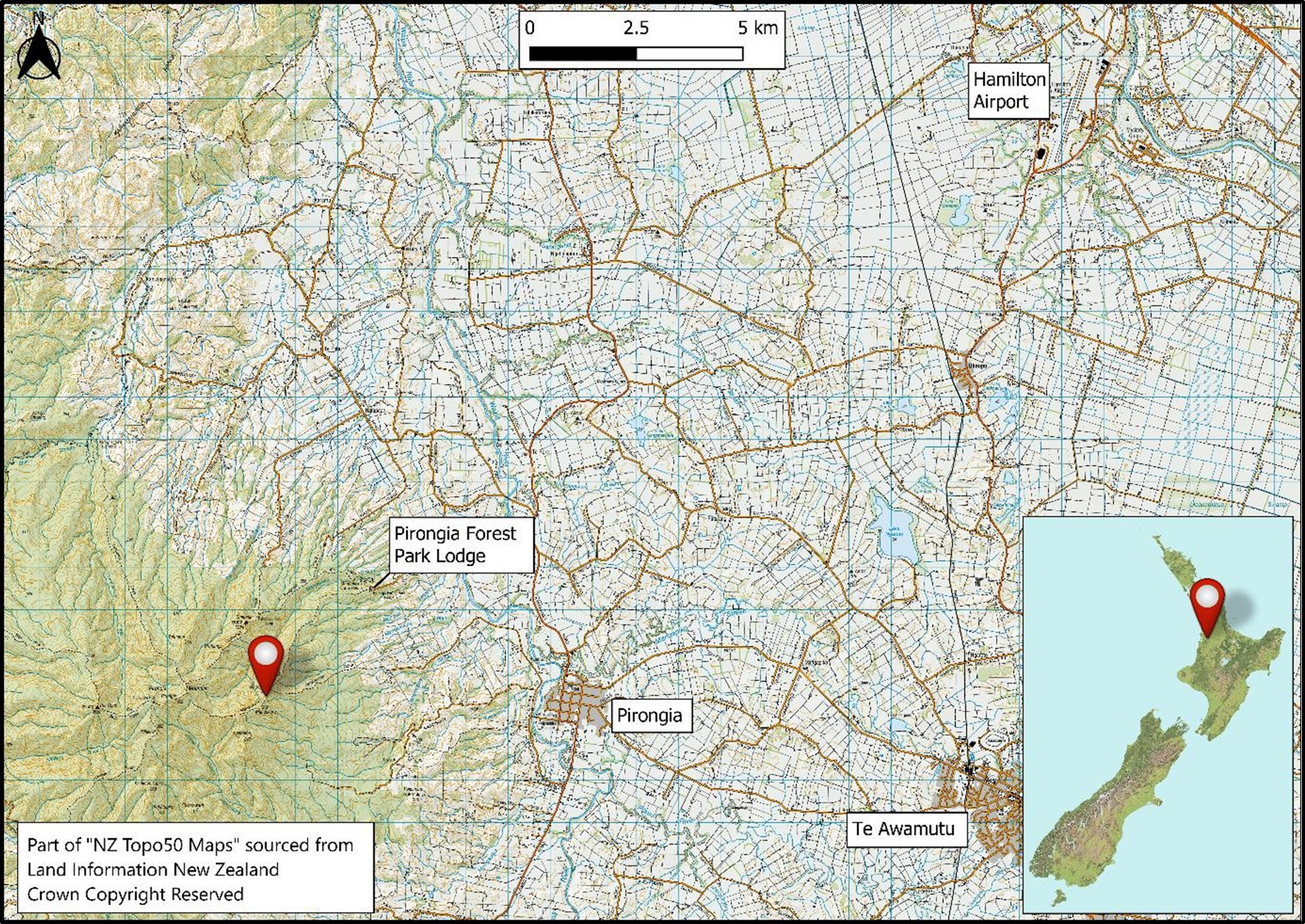
- The helicopter departed Hamilton Airport at 1620 for Te Awamutu. While enroute the pilot entered the patient’s global positioning system (GPS) coordinates into the helicopter’s GPS, which directed them to Mount Pirongia. While searching, the national Air Desk provided the crew with the patient’s mobile-phone number and coordinates from their Personal Locator Beacon, which assisted in locating the patient.
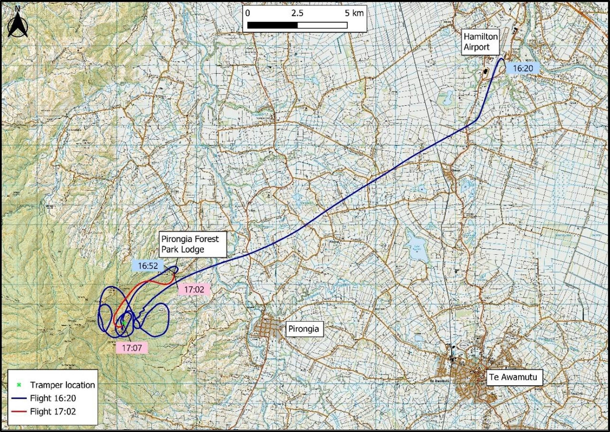
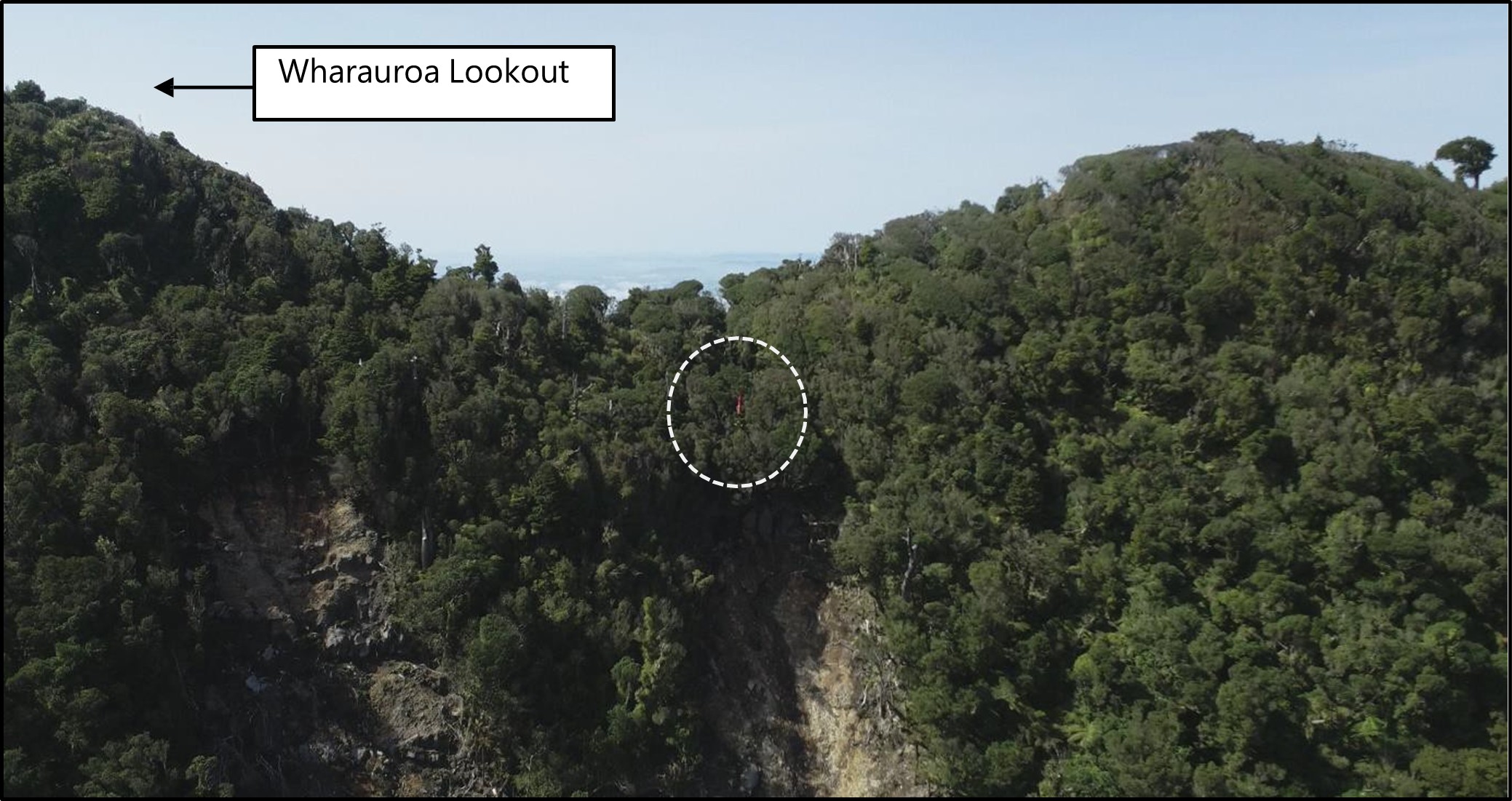
- At about 1645 the crew located the patient and their partner on the Mahaukura Track, situated below and on the southern side of Wharauroa lookout (see Figure 4). The crew conducted a reconnaissance of the site and found that there was no suitable place for the helicopter to land near the patient and that a winch extraction would be the most suitable method of recovery.
- The pilot then flew the helicopter to a nearby staging area at Pirongia Forest Park Lodge so that the crew could reconfigure the cabin for a winch operation. After the pilot landed and shut down the helicopter, the crew reconfigured the cabin and checked the winch was functional. They then discussed the procedures for recovering the patient by winch extraction.
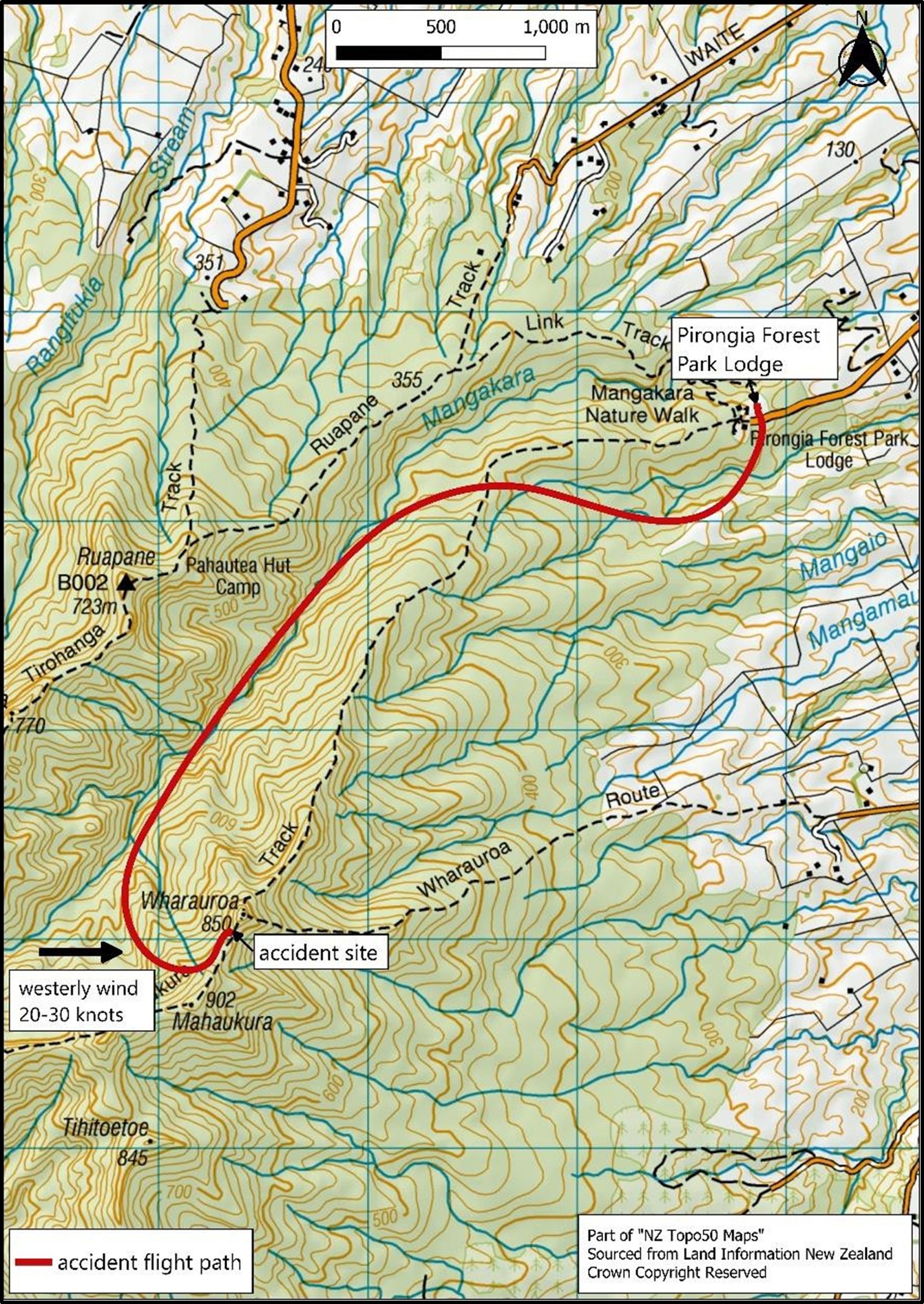
- At 1702 the helicopter departed Pirongia Forest Park Lodge and flew up the valley on the western side of Wharauroa Lookout. After passing abeam Wharauroa Lookout the helicopter entered a 180-degree climbing turn to the left and continued ascending to an altitude of 3000 feet (ft). The pilot continued the left turn before starting a descent onto final approach towards the patient on the windward side of a ridge (see Figure 4).
- An airspeed under 60 knots (kt) was required to open the rear sliding door safely in preparation for winching. During interviews the pilot recalled that, immediately after responding to the crew member’s request to open the door, the helicopter suddenly and unexpectedly dropped in height.
- Initially, the pilot tried to arrest the helicopter’s descent rate. When the pilot observed the treetops in their peripheral vision, they realised that an impact was imminent and shifted focus from recovering the high rate of descent to controlling the impact to minimise injury.
- At 1707, the helicopter descended through the tree canopy and impacted the terrain. It slid forward and down the slope about 1 metre (m), before coming to rest 7 m upslope of a pre-existing landslide.
- The crew exited the wreckage uninjured, and the paramedic promptly attended to the patient. The pilot and crew member subsequently assisted the paramedic to prepare the patient for a winch extraction. Between 1802 and 1840 the crew, patient and patient’s partner were uplifted and flown to Waikato Hospital by two rescue helicopters.
Personnel information
- The pilot held a Commercial Pilot Licence (CPL) for helicopters and a Private Pilot Licence (PPL) for aeroplanes. Before joining the operator in 2006 (the pilot was initially employed by Philips Search and Rescue Trust, before Search and Rescue Services Limited was established in June 2009 through the merger of various helicopter rescue trusts in the central North Island), they were a Senior Instructor Pilot and a Standardisation Instructor Pilot for the United States Army (US Army).
- At the time of the occurrence, they had accrued a total of 7257 flying hours, comprised of 6895.3 hours (h) in helicopters and 361.7 h in aeroplanes. They had flown about 48 h on the BK117 B-2 type of helicopter during the 90 days before the accident. The total flying experience on a BK117 B-2 was about 1928 h. The pilot held a Class 1 medical certificate valid to 20 March 2024 and was required to have half spectacles readily available during flight.
- The pilot had completed all the required competency assessments and was current at the time of the accident in accordance with New Zealand Civil Aviation Rules (CARs) and the operator’s exposition.
- The pilot’s competency check for winching was revalidated on 9 February 2023 and current until 15 February 2025. They had conducted recent winch operations on 11 September 2023 and 9 July 2023.
- All of the operator’s pilots are responsible for managing their fatigue levels by following the operator’s Fatigue Risk Management System and Alternative Flight and Duty Scheme. During interviews, the pilot reported having had 12 h free of duty and 9 h sleep before their shift, and advised they were well rested and in good health on the day of the accident.
- The operator’s procedures required crew to undergo drug and alcohol testing following any incident or accident. This test was carried out at Waikato Hospital about four hours after the accident and all crew returned negative (clear) results.
Aircraft information
- The Kawasaki BK117 B-2 helicopter, serial number 1109, registration ZK-HHJ, was constructed in 1996 by Kawasaki Heavy Industries Ltd (KHI), Japan.
- The BK117 helicopter was developed through a collaboration between Messerschmitt-Bolkow-Blohm (MBB) (now part of Airbus Group) of Germany and KHI. The MBB and KHI BK117 helicopters have separate type certificates with production lines in separate countries.
- The helicopter was fitted with two Honeywell LTS101-850B-2 turboshaft engines in accordance with a Supplemental Type Certificate (STC). The modification improves one-engine-inoperative (OEI) performance and all-engines-operating (AEO) performance at high altitudes and high temperatures.
- The helicopter was fitted with a Breeze-Eastern 600-pound (lb) hoist mounted on the right side of the fuselage, the same side as the pilot.
- The helicopter had been issued with a New Zealand non-terminating Certificate of Airworthiness in the Standard category on 2 November 2018.
- The helicopter’s logbooks recorded that the helicopter and engines had been maintained in accordance with the operator’s approved maintenance programme.
- A review of airworthiness had been carried out on 20 December 2022 with no reported defects. The next review of airworthiness was due on 20 December 2023.
- Airworthiness directives were checked against the Civil Aviation Authority of New Zealand (CAA) airworthiness directive schedule. No outstanding airworthiness directives applicable to the helicopter were observed.
- The helicopter’s logbooks showed that all scheduled maintenance had been carried out as required, and the helicopter had no recorded defects at the time of the accident.
- The BK117 B-2 helicopter has four main rotor blades made from glass and carbon-fibre reinforced plastics. Each main rotor blade is affixed to the main rotor head by both a primary and a secondary bolt. The rotor system is hingeless; the flexibility of the main rotor blades rather than mechanical hinges is used to accommodate their flapping and lead-lag motions.
- To boost the manual control inputs by the pilot, a dual hydraulic system is located on top of the cabin roof in front of the main transmission. For redundancy, the hydraulic unit consists of two separate systems that operate independently of each other. System one is used for normal operation and system two is the standby system. The two systems are linked so that in the event of a pressure drop or a control jam in system one, a changeover to system two occurs automatically and a caution light on the annunciator panel illuminates.
- An advisory, caution and warning annunciator panel is located below the instrument panel to alert the pilot to a system condition or failure. Whenever a yellow caution or red warning light illuminates on the annunciator panel, the master warning lights illuminate on both the upper left and right sides of the instrument panel. The purpose of this design is to capture the pilot’s attention and to indicate that a light on the annunciator panel has illuminated. In addition to a warning light on the annunciator panel, an aural warning will alert pilots to an engine failure or to low rotor RPM.
Meteorological information
- The Commission obtained a detailed analysis from Meteorological Service of New Zealand Ltd (MetService) of weather observations recorded on the day of the accident. The analysis showed there was no significant change in the weather conditions from the time the pilot conducted the site reconnaissance until the time of the accident.
- MetService concluded: At the time a high lay over northern New Zealand, bringing settled weather and westerly winds. The weather was fine enroute. However, there was cloud “cascading” over the summit of Mount Pirongia from the west, and then rapidly evaporating and clearing. The accident site was likely cloud free, with west to north westerly winds of around 20 kt and gusts to 30 kt possible. On the windward side of the immediate ridgeline, this wind flow would have resulted in orographic upslope winds and light turbulence.
- The patient advised Commission investigators that, around the time of the accident, the wind speed was variable from a westerly direction. They had observed extremely strong gusts at times. Throughout the day, there was a mixture of high cloud and clear sky. During the winch recovery, wisps of cloud were observed between Wharauroa and Mahaukura.
- Two rescue helicopters (MBB BK117 B-2 and Leonardo AW169) arrived at the site about an hour after the accident. The pilots of the two helicopters advised Commission investigators that the wind was strong westerly at about 20–30 kt, as recognised by the movement of trees, dust and clouds. One of the pilots said the wind speed and direction displayed on their helicopter’s Primary Flight Display (PFD) coincided with this observation. They also said that there was some cloud on the ridge line around the peak of Mount Pirongia.
Weight and balance
- When the crew reconfigured the helicopter cabin for winching operations, they were required to offload unneeded equipment to reduce the operational weight of the helicopter. The pilot calculated a load manifest before departing Hamilton Airport and again at the staging area at Pirongia Forest Park Lodge.
- The helicopter had a maximum certificated gross weight of 3350 kg and a minimum gross weight for flight of 1700 kg. CAR 133.71 states that a pilot performing an operation involving the suspension of a person beneath a helicopter must ensure that the helicopter is not operated at a weight in excess of 90% of its out of ground effect (OGE) hover weight. According to the hover OGE graph in the helicopter’s Flight Manual, the helicopter’s calculated maximum hover OGE weight at the patient’s location was 3350 kg. In accordance with CAR 133.71 the helicopter’s maximum permitted weight was therefore 3015 kg.
- Using the weights from the load manifest, the pilot calculated the helicopter to have weighed 2976.8 kg before departing from Pirongia Forest Park Lodge. This was 373.2 kg less than the maximum certified weight and 38.2 kg less than the calculated maximum hover OGE weight.
- The helicopter’s longitudinal and lateral centre of gravity positions and the maximum permitted weight were calculated to be within limits for the flight.
Recorded data
- The helicopter was not fitted with a voice or video recorder. These were not required by CARs.
- The helicopter was fitted with a Flightcell DZMx, located in view of the pilot. The DZMx recorded a range of flight data, including GPS position, aircraft pitch attitude, g-force and jerk (rate of change of g-force) once every second. The recorded data was extracted by Flightcell under supervision by Commission investigators, allowing the helicopter’s flight trajectory to be analysed. Flightcell reconstructed an animation of the helicopter's flight path, which assisted the investigation.
Site and wreckage information
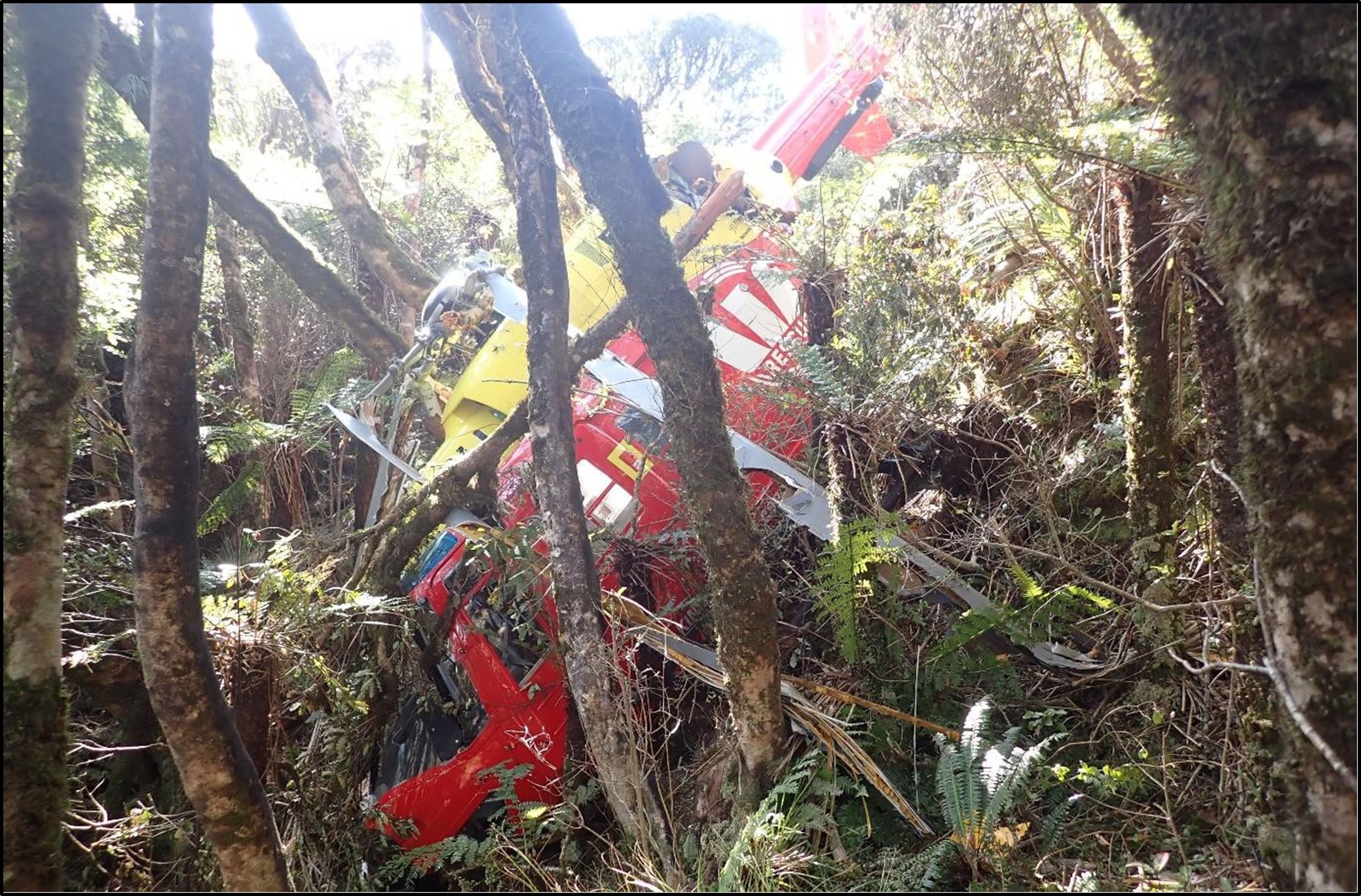
- The accident site was on Mount Pirongia on a west-facing escarpment covered by dense native forest, about 108 m southwest of Wharauroa Lookout (see Figure 5). The helicopter was sitting upright, wedged between trees below a ridge line (see Figure 6).
- Damage to trees at the site indicated that the helicopter had fallen almost vertically through the tree canopy. All the wreckage was contained within a 15 m radius of the main fuselage.
- The forward and aft cross-tubes of the landing-gear assembly had splayed outwards, causing the right side of the assembly to fracture in overload near the fuselage attachment fittings (see Figure 16 in Appendix 1).
- The markings on the trees surrounding the helicopter, and the damage to its main rotor blades, was characteristic of an impact with the blades having had high rotational energy. The outboard section of each main rotor blade was severely strike damaged. The main rotor blades had fractured outboard from the primary and secondary attachment bolts. One of the four main rotor blades had separated from the rotor head during the accident and was found lying next to the wreckage.
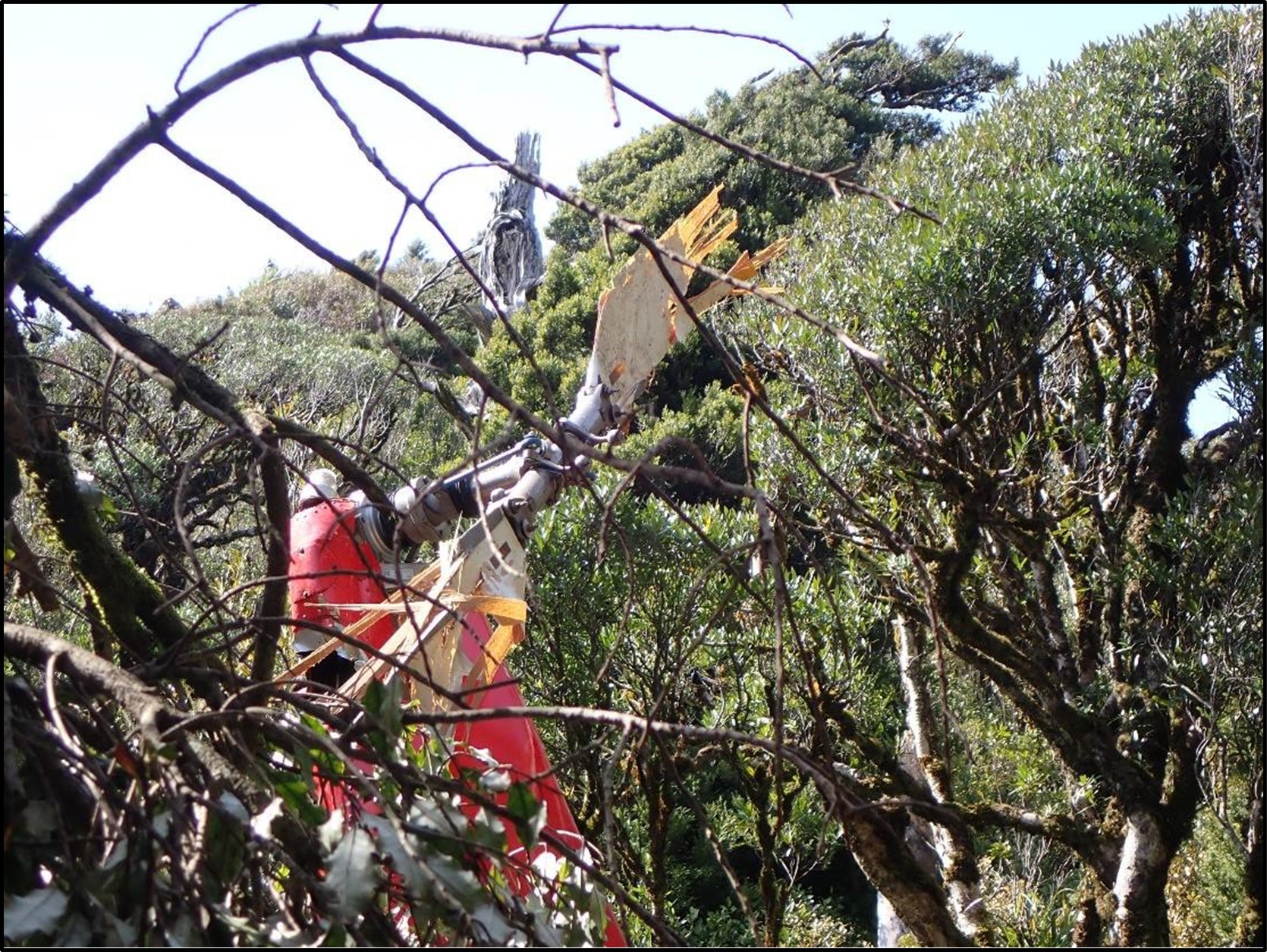
- Both tail rotor blades exhibited strike damage, but both were still attached to their mounting fork (see Figure 17 in Appendix 1).
- The engine drive shafts of both engines had exhibited torsional failure (see Figure 18 in Appendix 1). This is consistent with the engines having continued to drive the main rotor transmission under resistance as the main rotor blades struck the surrounding trees.
- The helicopter was equipped with an Artex C406-1 Emergency Locator Transmitter (ELT). The Rescue Coordination Centre New Zealand (RCCNZ) did not receive a notification from the ELT.
Survival aspects
- Injuries sustained in aircraft accidents arise from three distinct sources:
- excessive impact forces
- trauma from contact with injurious surfaces
- exposure to environmental factors such as fire or smoke
- The maximum impact force recorded during the accident sequence was 3.2 g. All three crew survived the accident without any injuries. This was attributed to the following factors:
- Statistical trends indicate that the absence of a post-impact fire is a critical factor in crash survivability. The helicopter’s fuel is stored in underfloor compartments using bladder-type fuel cells, which are designed to reduce the likelihood of a fuel leak in the event of an accident. The helicopter’s fuel cells withstood the impact and prevented post-impact fuel leakage, and therefore fire.
- Federal Aviation Administration (FAA), Title 14 Code of Federal Regulations (CFR) Part 29 (United States of America Title 14 CFR Part 29 Airworthiness Standards: Transport Category Rotorcraft), prescribes airworthiness standards for the issue of type certificates, and the changes required to those certificates for the rotorcraft to be certificated as a transport category rotorcraft. At the time of design, the BK117 structure was designed to withstand higher loads than those specified by Title 14 CFR Part 29. The energy-absorbing structure of the helicopter’s cabin maintained sufficient strength during the accident to prevent structural collapse and/or penetration of the main rotor transmission and engines into the occupied spaces inside the cabin.
- Research on helicopter accidents indicates that, in most survivable accidents, the primary crash force is vertically downwards. The helicopter had fallen through the tree canopy almost vertically and its landing gear assembly impacted the terrain, causing the cross tubes to splay outwards, as intended, to cushion the impact.
- When the pilot realised that impact was imminent, they shifted focus from recovering from VRS to controlling the impact to minimise injury. They oriented the helicopter so that the crash force would be directed as vertically as possible through the helicopter’s structure, notwithstanding the steep slope of the terrain at the accident site.
Organisational information
- Search and Rescue Services Limited is the provider and operator of air ambulance operations in the Central North Island, New Zealand. Under its contract with National Ambulance Sector Office (NASO), helicopter crews respond to requests for emergency pre-hospital treatment and transportation of acutely unwell patients. Dispatch to these missions is authorised and coordinated by the national Air Desk.
- Search and Rescue Services Limited also provides:
- Inter-hospital transfers (the transportation and clinical care of patients between hospitals), a process coordinated by Health New Zealand | Te Whatu Ora (HNZ) in collaboration with the respective hospitals
- Search and rescue services in collaboration with New Zealand Police and RCCNZ
Vortex Ring State (VRS)
- VRS is a hazardous aerodynamic phenomenon that a helicopter can encounter when in steep descending flight at low forward speed and during manoeuvres at low forward speed. The onset of the VRS can lead to a rapid loss of lift and subsequently to a sudden increase in the helicopter’s rate of descent. If not detected, the helicopter can rapidly enter an unstable condition characterised by thrust fluctuations, decreased control authority and a significant increase in its rate of descent.
- The existence of VRS is universal to all rotor designs. The major characteristics of VRS are determined principally by the disc loading of the rotor. The detailed design of the rotor, such as the twist of its blades and blade-tip shape, have a secondary influence on the characteristics of VRS.
- The VRS domain extent for several well-known conventional helicopters is compared in Figure 7. The coloured line indicates the VRS onset boundary for each specific helicopter, as defined by its vertical and forward speeds. So, for instance, the BK117 helicopter will encounter VRS if its trajectory takes it into the region of the diagram that is shaded in red. Using similar logic, the large, heavy CH-53E military transport helicopter might experience VRS at descent rates between 1350 and 6000 ft/min, when flying at a speed less than 34 kt; a small helicopter, such as the Robinson R22, would only encounter VRS at descent rates between 700 and 3100 ft/min, when flying at speeds less than 17 kt.
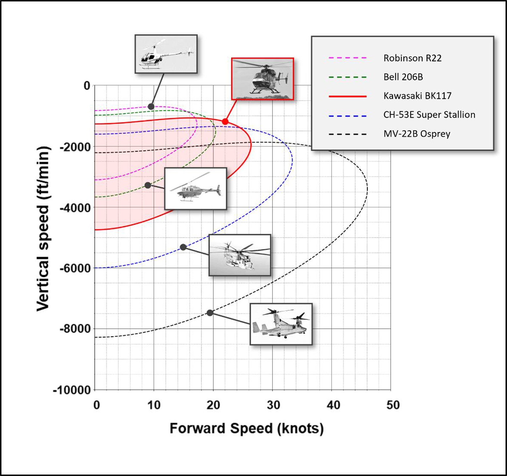
(Credit: Dr Richard E. Brown, Sophrodyne Aerospace)
Why does Vortex Ring State occur?
- In normal flight, a helicopter’s main rotor creates a long, cylindrical wake that streams down into the flow below and behind the main rotor (see Figure 8). The wake from a helicopter’s main rotor is inherently unstable. This instability causes the orderly structure of the wake eventually to break down into a highly turbulent, chaotic flow. In normal flight this breakdown occurs below and behind the helicopter and has very little influence on the aerodynamics of the main rotor itself.
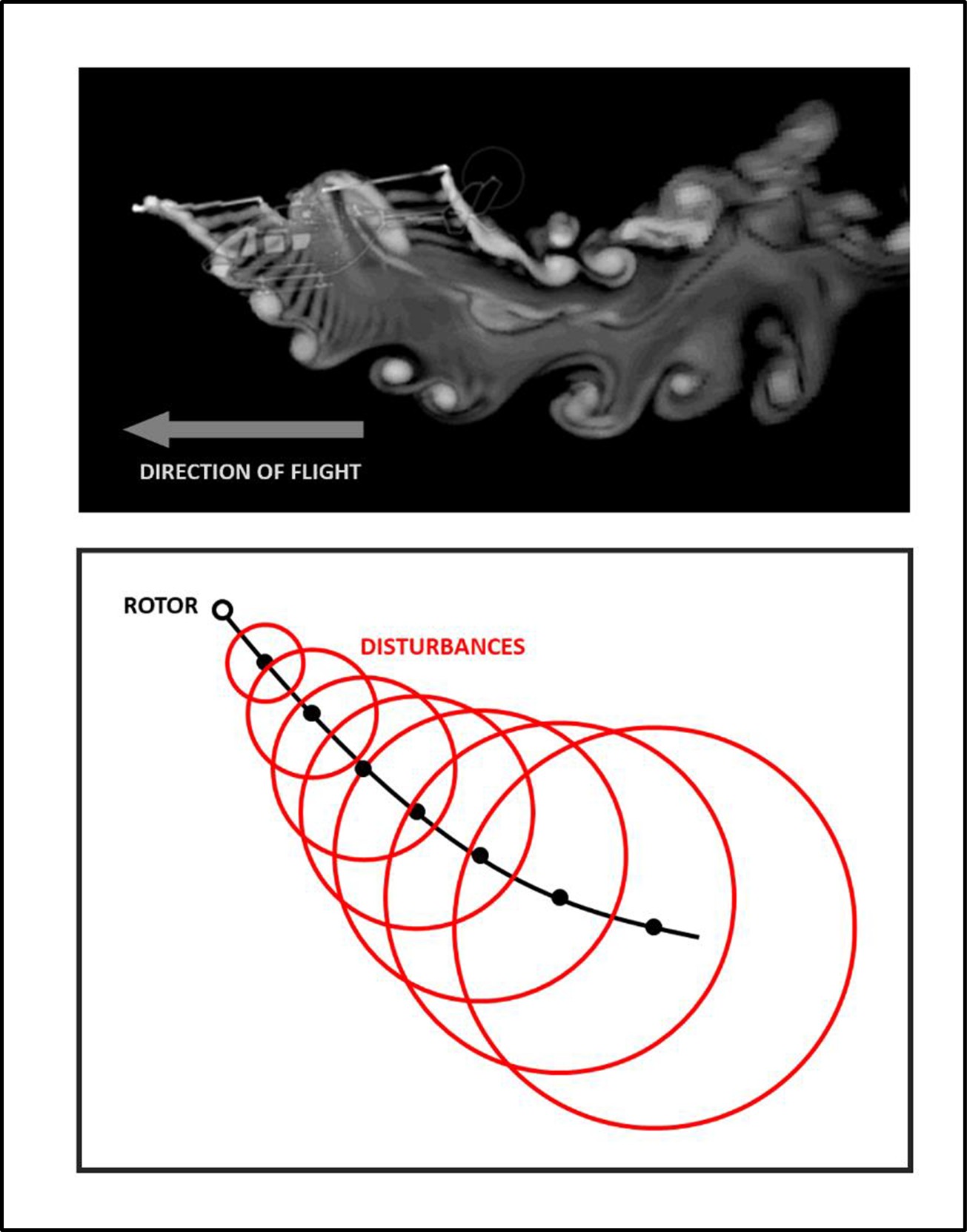
- A physical representation of the main rotor wake with the helicopter in forward flight is demonstrated in Figure 8. The image shows how the wake near the main rotor initially has an ordered cylindrical shape and how, further away from the helicopter, the wake becomes increasingly more disordered as its inherent instability starts to take hold. The figure at the bottom shows an idealisation of this process.
- Within a range of descent rates and forward air speeds, the instability of the wake is able to catch up with the main rotor, causing the wake to collapse into a toroidal form, known as VRS. The onset of VRS is responsible for a sudden decline in the lift generated by the rotor. In practice this usually causes the helicopter to descend rapidly unless appropriate action is taken to recover the helicopter into normal flight.
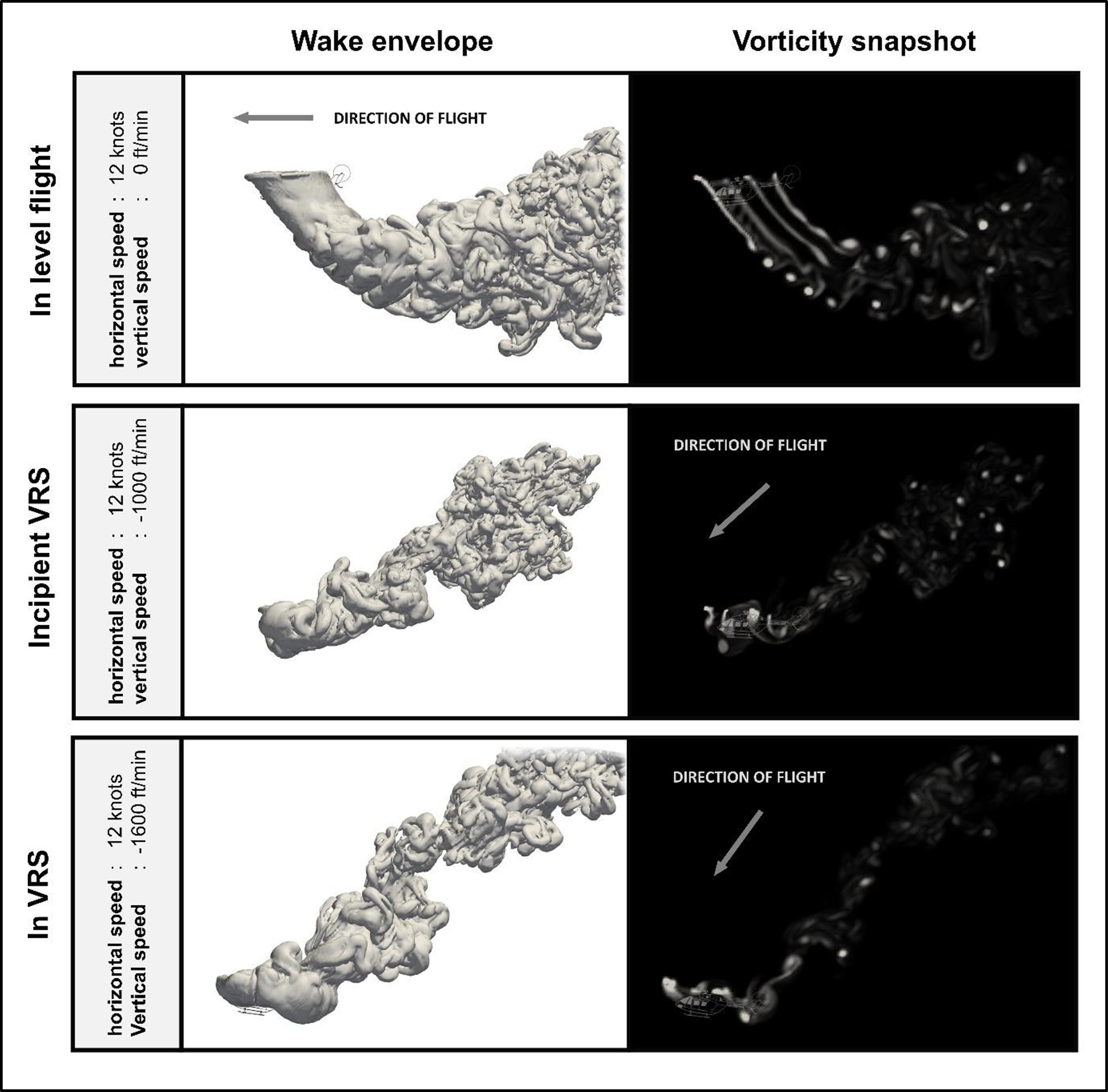
- A comparison of a helicopter’s main rotor wake structure in level flight at a speed of 12 kt is demonstrated in Figure 9. The middle image shows the structure of the wake just before VRS onset. The disturbances in the main rotor wake have practically caught up with the main rotor. The bottom image shows the helicopter relatively deep within VRS. The wake has transitioned into the toroidal recirculatory form that is associated with VRS.
Recovery from Vortex Ring State
- The onset of VRS is responsible for a sudden decline in the lift generated by the main rotor and usually causes the helicopter to descend rapidly unless action is taken to recover the helicopter.
- A pilot’s intuitive response to the sudden and unexpected increase in descent rate that accompanies VRS onset is usually to increase collective. However, this usually energises the toroidal form associated with VRS and ends up exacerbating the rate of descent. Hence the pilot’s conscious action is required to suppress their natural response and to apply a proper technique to recover from VRS.
-
The two most common recovery techniques that pilots are currently taught are the ‘traditional’ technique and the Vuichard recovery technique. The FAA’s Helicopter flying handbook (Federal Aviation Administration, 2019) details both these methods of VRS recovery:
The traditional recovery is accomplished by increasing airspeed, and/or partially lowering collective to exit the vortex.
In most helicopters, lateral cyclic thrust combined with an increase in power and lateral antitorque thrust will produce the quickest exit from the hazard. This technique, known as the Vuichard recovery (named after the Swiss examiner from the Federal Office of Civil Aviation who developed it) recovers by eliminating the descent rate as opposed to exiting the vortex.
Settling with power
- Because of inconsistent terminology in aviation literature (Federal Aviation Administration, 2019) (Wagtendonk, 2006), pilots can confuse VRS with other phenomena such as ‘settling with power’ or ‘power settling’. These phenomena can all be encountered in low-speed flight and the terms have historically been used interchangeably. However, the origins of ‘settling with power or ‘power settling’ are different from those that precipitate the VRS.
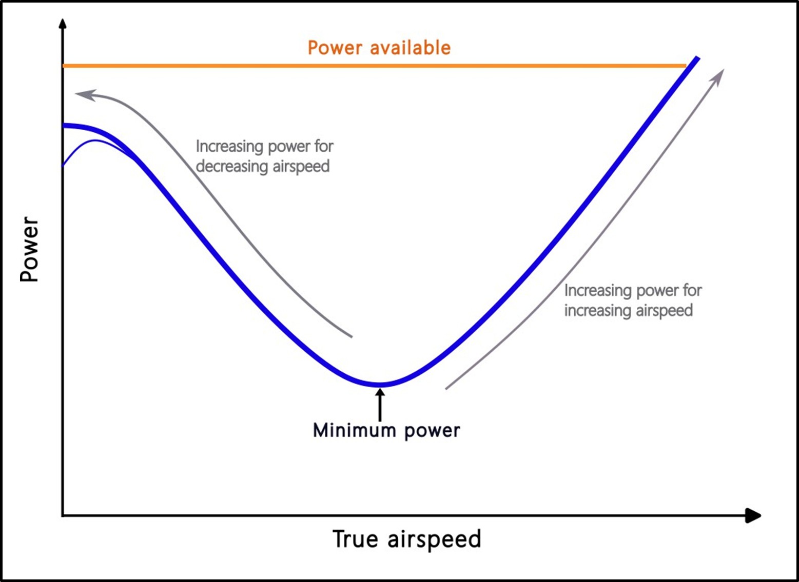
- The power required to sustain level flight increases as the forward speed of the helicopter is reduced below the minimum power setting for level flight (see Figure 10). If the engine(s) cannot provide the necessary power, then the helicopter will begin to descend or settle. This is not VRS but rather a condition where the engine(s) have reached their maximum available power limit. The power required exceeds the power available.
- In certain circumstances, if the airspeed is slow enough, the descent rate can build up to the point at which VRS is eventually encountered in its aerodynamic form (see paragraphs 2.55 to 2.57).
Previous occurrences
- According to the National Transportation Safety Board (NTSB) report database, from 2008 to 2021, 48 helicopter accidents in the United States of America involved VRS encounters. The data collected only represents reported accidents and does not include VRS encounters where the pilots performed a successful recovery manoeuvre and avoided damage to the helicopter or injury to the crew. Therefore, the incidence of VRS is at a higher level than these numbers indicate.
Analysis Tātaritanga
Introduction
- The national Air Desk dispatched the helicopter from Hamilton Airport to retrieve a trauma patient at Mount Pirongia. Upon locating the patient, the crew devised a retrieval plan and flew to a nearby staging area to reconfigure the helicopter for winching. The retrieval plan required the pilot to manoeuvre the helicopter into a position from which the patient could be winched up. During the final approach the helicopter rapidly and unexpectedly dropped in height, resulting in the helicopter impacting the terrain.
- The helicopter’s trajectory and pitch attitude, combined with the orographic uplift conditions on the windward side of the ridge that the helicopter was flying along, increased the risk of the helicopter entering VRS. Despite the hazard it poses to flight safety, VRS generally remains a poorly understood aerodynamic phenomenon that can be encountered during the descent and landing phases of flight, and during manoeuvres at low forward airspeeds.
- Current helicopter certification standards do not require manufacturers to determine the range of flight conditions and operational parameters above which a helicopter might be susceptible to VRS. In the absence of this information, and particularly if it has not been incorporated into the applicable rotorcraft flight manual, pilots are less likely to be able to accurately determine the range of flight conditions in which a helicopter might be susceptible to VRS.
- The following section analyses the circumstances surrounding the event to identify those factors that increased the likelihood of the event occurring or increased the severity of its outcome. It also examines any safety issues that have the potential to adversely affect future operations.
What happened
- The objective of the rescue mission was to recover a trauma patient located on the Mahaukura Track on Mount Pirongia.
- When the helicopter arrived at the patient’s location, the pilot conducted a site reconnaissance and concluded that the wind was from a westerly direction, but the speed was negligible. There were sufficient power margins for the helicopter’s safe operation during winching. The pilot then flew the helicopter to Mount Pirongia Forest Park Lodge and the crew reconfigured the cabin for a winch operation.
- The pilot intended to conduct the recovery by ascending to the patient’s altitude, decelerating on final approach and then positioning the helicopter about 100 ft above the patient. The crew member would then guide the pilot to the appropriate position for a winch extraction.\
- After the helicopter departed the Lodge, the pilot flew it up the valley on the western side of Wharauroa Lookout. The pilot was located in the front right seat, a paramedic in the left rear-facing seat of the rear cabin, and a crew member on the floor of the rear cabin beside the right sliding door. The crew member was restrained by a harness and lanyard connected to the helicopter. The crew described the wind conditions as non-turbulent as the helicopter proceeded up the valley.
- After passing abeam Wharauroa Lookout, the helicopter entered a 180 -degree climbing turn to the left and continued ascending to an altitude of 3000 ft. The patient was located below and on the southern side of Wharauroa Lookout at an altitude of 2640 ft. This required the helicopter to descend about 260 ft to position itself 100 ft overhead the patient. Despite some cloud around the summit of Mount Pirongia, the patient’s location remained clear and the pilot continued the left turn before starting a descent onto final approach on the windward side of the ridge leading up to the Lookout.
- The helicopter’s speed progressively decreased during its final approach, as depicted in Figure 11, which illustrates the helicopters trajectory. At 17:06:51 the helicopter’s pitch angle reached a maximum of 19.5° (nose up). This in turn reduced the helicopter’s speed and increased its rate of descent.
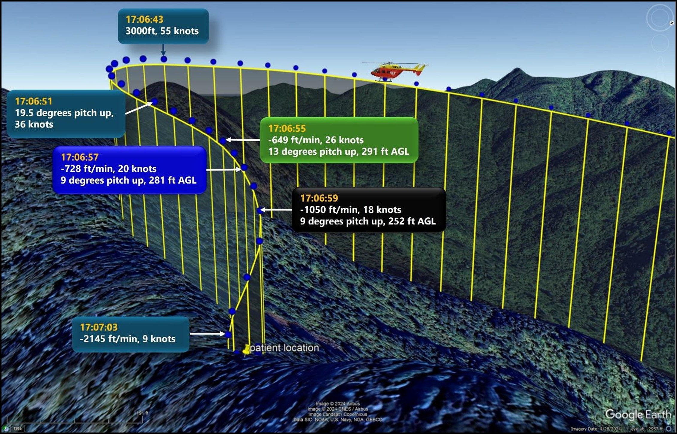
- A maximum airspeed of 60 kt was required to open the sliding door safely in preparation for winching. During interview, the crew member recalled asking the pilot if the speed was okay to open the door. The pilot replied ‘’we are a little too hot’’ (see paragraph 3.20 for an explanation) but was unable to complete their response to the crew member before the helicopter rapidly and unexpectedly dropped in height.
- The flight data downloaded from the Flightcell DZMx shows the sudden drop in height occurred at 17:06:55, when the helicopter was at about 291 ft AGL. At this time the helicopter had a descent rate of 649 ft/min and a groundspeed of 25.8 kt. The helicopter’s pitch attitude was 13° (nose up) on a heading of 25° true.
- During interview, the pilot recalled that the cyclic25 and collective controls lacked responsiveness during the rapid descent. They suspected VRS and attempted to recover and arrest the high rate of descent of the helicopter by initially applying the traditional recovery technique. Upon realising that there was insufficient height available, the pilot immediately attempted a second technique, called the Vuichard recovery technique.
- The wind by this stage was 20 kt and gusting 30 kt from a westerly direction, resulting in a crosswind from the helicopter’s left rear quarter. At 17:06:59 the helicopter’s heading changed relative to the wind direction, to where the wind acted from behind (tailwind). The helicopter increasingly veered to the right and proceeded to pitch nose-down. The helicopter reached a maximum descent rate of 2145 ft/min with a forward groundspeed of 9 kt.
- Realising that impact with the terrain was imminent, the pilot focused on controlling the descent through the tree canopy to minimise the potential forces on impact. The pilot pitched the helicopter nose-down to prevent the tail from contacting the trees first, thus averting a potential slew of the helicopter. The helicopter continued turning right. The pilot was able to manoeuvre the helicopter between the trees before descending through the tree canopy.
- At 1707, the helicopter impacted the terrain and slid down a slope about a metre, before coming to rest, seven metres upslope of a pre-existing landslide.
Why did the helicopter impact the terrain
Engine or flight-control failures
- Based on the following evidence it was exceptionally unlikely that an engine or flight-control failure caused the helicopter to impact the terrain.
- the drive shafts of both engines had twisted and separated, consistent with the engines having continued to drive the main rotor transmission under resistance as the main rotor blades struck the surrounding trees.
- the trees surrounding the helicopter were damaged by the main rotor blades and the severity of the damage was characteristic of an impact with the main rotor blades still having high rotational energy.
- the pilot said in interview that the helicopter was performing perfectly, that there were no aural warnings or warning lights and that they had to shut the engines down after impact.
- post-accident inspection showed that the helicopter’s primary flight controls had retained continuity and had been assisted by hydraulics up to the point of impact.
Pilot actions
- New Zealand CARs require each holder of an Air Operator’s Certificate to establish an operational competency assessment programme for flight crew and crew members, to ensure that they are trained and competent to perform their assigned duties. During interview the operator’s training manager explained how VRS was integrated into the operator’s training syllabus, with emphasis on recognition and avoidance. Both the Vuichard and traditional recovery techniques were included; however, demonstrations of actual in-flight recovery from VRS were not practised following the publication of Airbus Helicopter’s Safety Information Notice No 3463-S-00 (Airbus, 2022). This notice recommends that operators do not intentionally place the helicopter in fully developed VRS because of the aerodynamic loads imposed on the helicopter.
- The operator’s Standard Operating Procedures (SOP) provided detailed procedures, guidelines and allocation of responsibilities amongst the crew during various phases of flight operations. The SOP outlined that winching procedures were not rigid rules nor the only way to accomplish a task, because of the inherent risks and dynamic environment associated with winching. The SOPs also incorporated crew resource management (CRM) principles to assist the crew in forming a shared mental model of their situation and environment. Although the operator’s SOP for a standard winch circuit (see Appendix 2) was appropriate for most situations, the operator allowed the crew to exercise their professional judgement in choosing and modifying the appropriate winching tasks to the prevailing circumstances and conditions.
- The pilot’s response to the crew member’s request to open the sliding door was that “we are a little too hot”. As airspeed is the only restriction to opening the door, the crew member interpreted the pilot’s response to mean the speed was above 60 kt during this time. The pilot’s last remembered instrument scan occurred during the left base turn onto final approach, noting the airspeed at this time to be around 50 kt. Reviewing the data from the Flightcell DZMx shows that the helicopter’s groundspeed during the left base turn was around 55 kt. The helicopter continued to decelerate while on final approach (see Figure 11).
- During interview, the pilot explained that they wanted to keep the door closed because they did not like having the door open when the helicopter was not in level flight. Their intention was to complete the base turn and to reduce speed before the door was opened, thus avoiding any potential blast of wind entering the cabin as the helicopter approached the winch position.
- During the winch circuit the paramedic and crew member were attempting to resolve an issue with the handheld radio, which diverted their attention from preparing the cabin, and providing commentary to the pilot on the patient’s position. Following the start of the turn, the pilot was unable to establish the stable approach profile as recommended in the operator’s SOP, nor were all the pre-winch tasks completed with 100 m still to run to the patient’s location. During this critical phase of flight, the pilot was under the assumption the helicopter was at the same altitude as the patient and that a descent before reaching the patient would not be required. At this time, the pilot’s visual attention was primarily focused outside of the cockpit on the patient’s location. As a result of a reduced instrument scan, indications that the helicopter was entering conditions conducive to VRS were not immediately recognised.
- The pilot said during interview that they used a ‘rule of thumb’ to avoid VRS, based on speed, descent rates and engine power, that they had learnt in the US Army. This rule of thumb made no allowance for the type of helicopter that they were flying, nor for the actual disc loading of the rotor. Furthermore, there was no consideration of the effect of orographic winds nor for how the helicopter's pitch attitude might have been conducive to earlier-than-anticipated VRS onset.
- Flight manoeuvres that are known to precipitate VRS are often performed at relatively low altitudes and are associated with descents and landings (Sotiropoulos- Georgiopoulos, et al., 2023). The timely identification of the symptoms of incipient VRS is critical to recovery. The pilot initially tried to arrest the descent rate of the helicopter by applying the traditional recovery technique that they had taught and demonstrated during their time in the US Army. When this did not resolve the situation, they tried the Vuichard recovery technique. The height above terrain at VRS onset was 291 ft AGL, which suggests the pilot had very little height or time to successfully execute either recovery technique.
- Although training in VRS recovery is essential, it should not be a substitute for training pilots to identify the conditions that can lead to premature entry into VRS. In New Zealand, the CAA has published information and guidance (Civil Aviation Authority of New Zealand, 2016, 2018 and 2020) to raise awareness of VRS and has conducted workshops on VRS recovery. The Commission considers that better education regarding the factors that can induce VRS would equip pilots with the ability to better detect and avoid the onset of VRS as identified in this investigation.
Evidence the helicopter entered Vortex Ring State
- The size and extent of the region of the flight envelope26 in which a helicopter can encounter VRS is determined principally by the disc loading of the rotor, as well as by the local atmospheric conditions. A helicopter will encounter VRS if its trajectory takes it into this region. The helicopter’s flightpath before the accident was conducive to VRS. Orographic uplift across the ridge along which the helicopter was flying and the helicopter’s pitch attitude during its deceleration both contributed to the early onset of VRS. This section describes the methodology that was used to calculate the speed and descent rate required for the helicopter to enter VRS. The analysis shows how important the helicopter’s pitch attitude and the effects of the wind were, especially when descending adjacent to the ridge line, in creating a set of flight conditions in which the aircraft would have been particularly susceptible to VRS.
How the VRS onset boundary was calculated for the accident flight
- The location of the VRS onset boundary on the flight envelope (see Figure 12) was calculated using a mathematical model that recognises the inherent instability of the rotor wake as fundamentally responsible for the onset of VRS. The region of the flight envelope in which this model predicts VRS might be encountered correlates well against a wide range of flight tests and laboratory data for various types of rotorcraft. (Ahlin, G.A & Brown, R.E., 2004. Predicting the Onset of the Vortex Ring State under Accelerated Flight Conditions. Newman, et al, 2003. Predicting the Onset of Wake Breakdown for Rotors in Descending Flight, Journal of the American Helicopter Society, Volume 48)
- Aerospace engineer Dr Richard E. Brown from Sophrodyne Aerospace provided expert advice in locating the VRS onset boundary on the flight envelope for the accident flight. Dr Richard E. Brown is an experienced aerospace engineer, with a 30-year record in modelling and understanding aircraft and helicopter aerodynamics, aerospace education, and air vehicle analysis and design. Dr Brown has published over 100 technical papers in the field of modelling and simulation of aircraft systems and is a recipient of both the Royal Aeronautical Society’s bronze medal for contributions to understanding rotorcraft aerodynamics, and the Vertical Flight Society’s award for extraordinary work in vertical flight. Dr Brown is the originator of our modern conception of how VRS develops on helicopter rotors and is actively involved in extending our understanding of the phenomenon in order to improve the safety of rotorcraft operations.
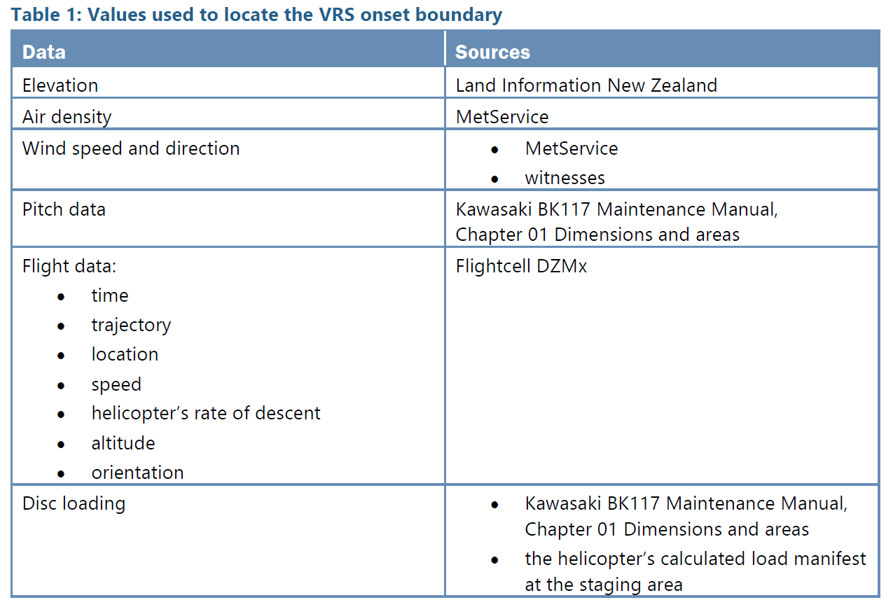
- The sources that were used to yield values for the parameters that define the location of the VRS onset boundary on the flight envelope for the accident flight are listed in Table 1.
The helicopter’s flight trajectory
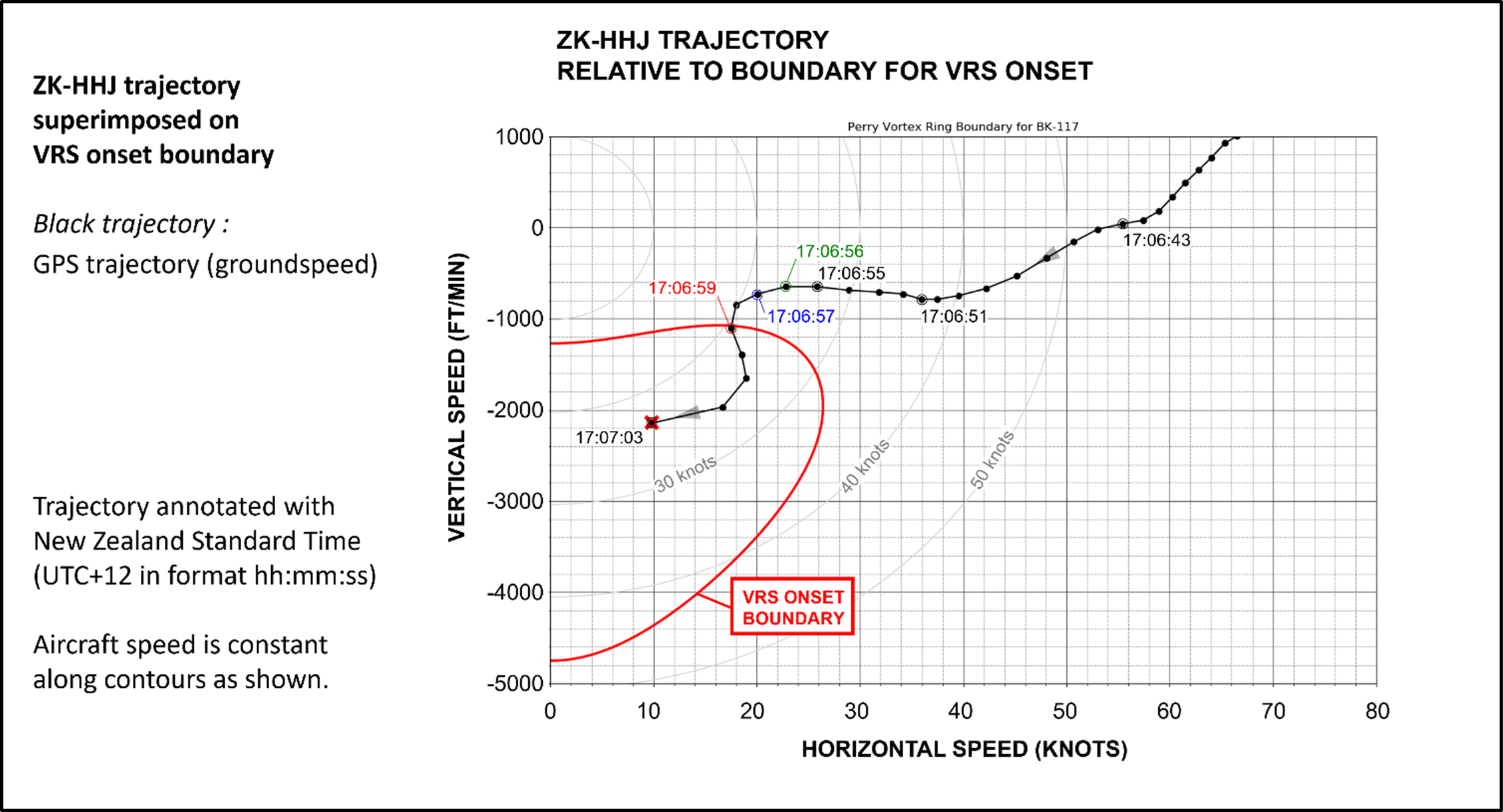
- Figure 12 shows the location of the boundary for VRS onset on the flight envelope, as defined by mapping the location of flight conditions at which the disturbances to the wake structure are able to reach the main rotor. If the axes in this figure are interpreted as the speeds of the helicopter relative to the ground, then the figure suggests that a BK117 B-2 helicopter with the weight and geometric characteristics of the accident helicopter, when flying at the altitude of the accident site, would have encountered VRS when flying at descent rates between 1050 and 4750 ft/min if flying horizontally at speeds less than 27 kt (groundspeed). The black line shows the horizontal speed and descent rate of the accident helicopter at various points along its final trajectory, as measured relative to the ground. According to the diagram, the helicopter will have entered VRS at 17:06:59 by crossing the onset boundary with a descent rate of 1050 ft/min and a groundspeed of 18 kt.
The effect of wind as a contributing factor to VRS
- The analysis up to now shows the helicopter’s trajectory in terms of groundspeed or, equivalently, airspeed in the absence of any wind. This section adds the effects of the wind in determining the helicopter’s trajectory relative to the VRS onset boundary for the helicopter.
- An analysis of the wind conditions at the time of the accident concluded that the wind speed was 20 kt, with gusts to 30 kt, from a westerly direction. The topography would have induced an upward component of wind flow relative to the helicopter’s trajectory, known as orographic uplift. This upwards component of the wind would have appeared to the rotor as an increase in its effective descent rate. The blue trajectory (see Figure 13) depicts the helicopter’s velocity, represented as a horizontal airspeed and descent rate, factoring in the influence of wind. This figure shows that, on accounting for the effect of the wind, the helicopter would have encountered VRS at 17:06:57, two seconds earlier than if the effects of the wind were not accounted for. By referring back to the trajectory shown in Figure 12 it can be inferred that the helicopter would have entered VRS at a substantially lower descent rate and higher forward speed (728 ft/min with a groundspeed of 20 kt) compared with the effects of the wind being omitted from the analysis.
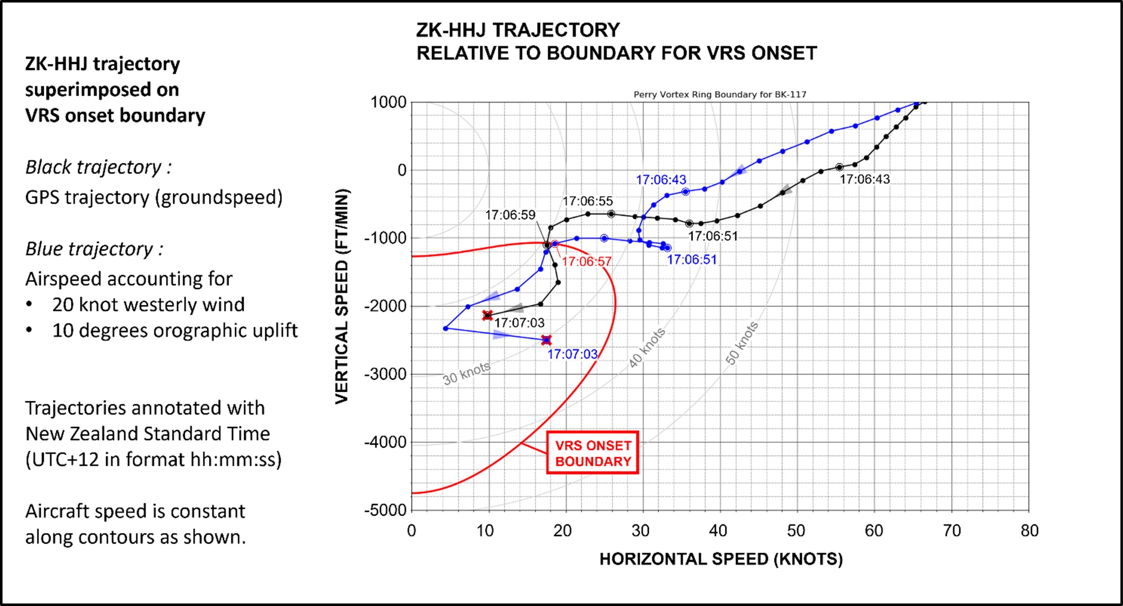
- An important factor was the change in the helicopter’s heading around 17:06:59, causing a shift in the wind to blow from behind the helicopter (tail wind), effectively reducing the helicopter’s airspeed. This shift in the relative wind contributed to the helicopter penetrating more deeply into VRS than if the heading of the helicopter had remained unchanged. As a result, the pilot would have experienced significantly exacerbated symptoms of VRS, as well as potentially greater difficulty in recovering to normal flight.
The effect of pitch attitude as a contributing factor to VRS
- The analysis can be refined further by accounting for changes in the pitch attitude of the helicopter along the flight trajectory. The precise location on the flight envelope of the boundary for VRS onset is defined by the velocity components relative to the rotor rather than the velocity components relative to the ground or to the helicopter. The helicopter’s nose-up flare while descending towards the patient increased the upwards component of air velocity through the rotor, increasing its effective descent rate and bringing the helicopter closer to the onset of VRS.
- In Figure 14, the green trajectory denotes the airspeed and descent rate as measured relative to the helicopter’s rotor, accounting for the changes in pitch attitude of the helicopter, while descending along the ridge line. The effective inclination of the rotor to the airflow was calculated by subtracting the helicopter’s mast inclination angle (5°) from the helicopter’s pitch attitude, as recorded by the Flightcell DZMx.
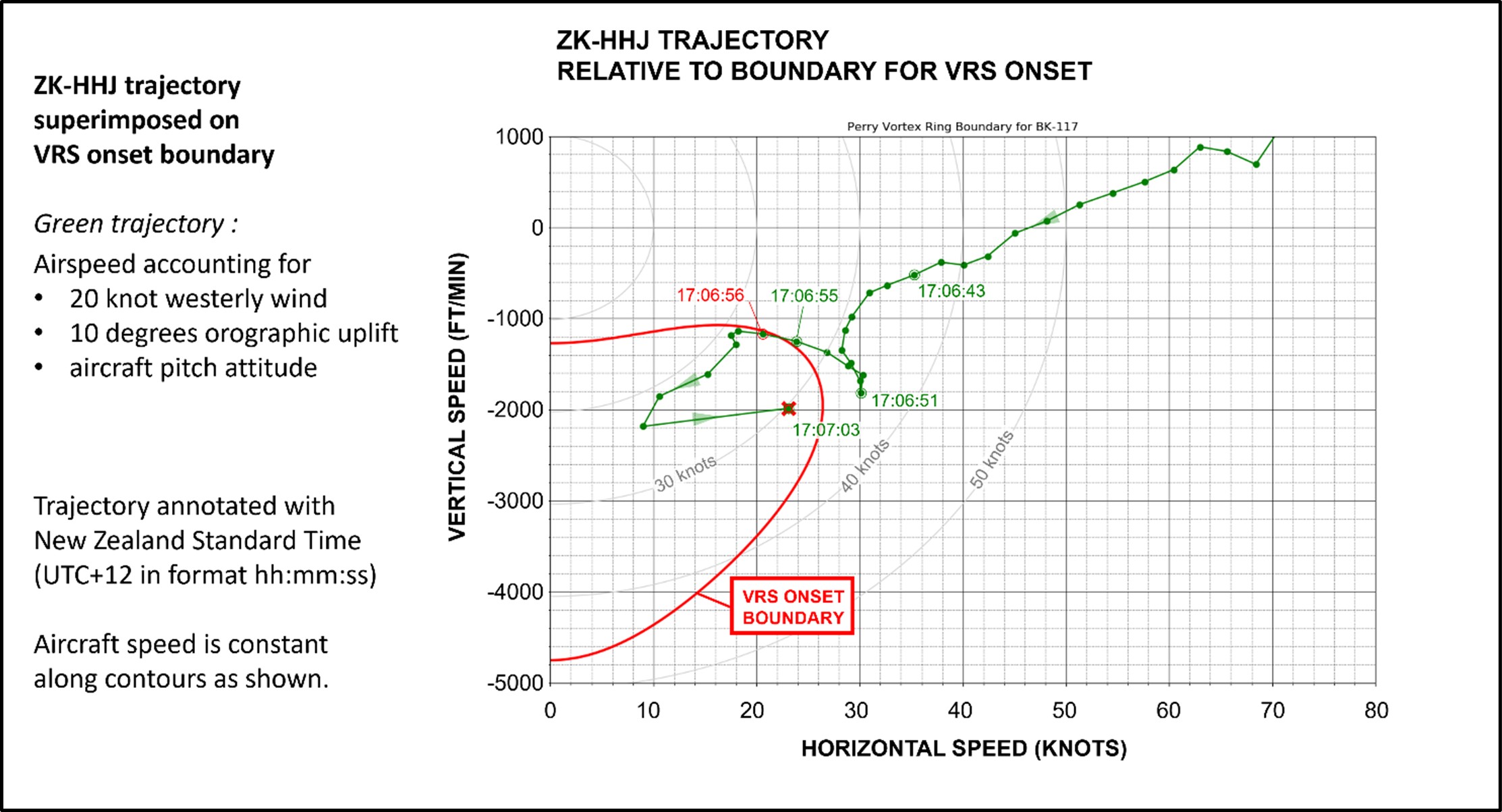
- At 17:06:51 the helicopter’s pitch attitude reached a maximum of 19.5°. The analysis presented in Figure 14 then shows that the helicopter would have crossed the VRS onset boundary sometime between 17:06:55 and 17:06:56, 3.5–4 seconds earlier than if the pitch attitude and wind were ignored in the analysis. Referring back to the speeds relative to the ground (the black trajectory in Figure 12), the helicopter would have entered VRS at a descent rate of 649 ft/min with a groundspeed of 25.8 kt.
Conclusion
- It is virtually certain that the helicopter entered VRS while descending on the windward side of the ridgeline to recover the patient. The helicopter’s trajectory led it into that part of the flight envelope where its combination of forward speed and descent rate precipitated the onset of VRS. After accounting for the orographic uplift over the ridge along which the helicopter was flying, as well as the helicopter’s pitch attitude, VRS onset would have occurred while flying at a descent rate of 649 ft/min with a forward speed relative to the ground of 25.8 kt.
- The analysis was able to establish the flight conditions for VRS onset, but recovery from VRS back into normal flight conditions is governed by different physical mechanisms and cannot be reliably predicted using the methodology presented here. To escape from VRS, the pilot is required to suppress those mechanisms that feed the recirculatory flow around the rotor and to re-establish the rotor wake in its normal operating state. Several piloting techniques, including the ‘traditional’ recovery and the more recent ‘Vuichard’ recovery technique, require the pilot to be aware of the early symptoms of VRS onset and to be trained in the application of the techniques.
Vortex Ring State (VRS) awareness
Safety issue: The helicopter’s Flight Manual did not include sufficient guidance for pilots to recognise and avoid the onset of VRS. This increased the risk of pilots inadvertently entering conditions conducive to VRS.
- VRS has been recognised as a hazard to the safe operation of a helicopter by aerodynamicists and helicopter designers since the early days of helicopter flight. Since then, ongoing research, supported by simulation and flight testing, has continued to refine the helicopter industry’s understanding of where and how VRS can be encountered during flight.
- Flight manoeuvres that are known to precipitate VRS are predominantly those associated with the descent and landing phases of flight and thus are often performed at relatively low height AGL. Recognising and avoiding the combination of flight conditions that is conducive to VRS is essential for preventing the helicopter from entering VRS.
- The Commission found that the helicopter’s Flight Manual did not contain the necessary guidance for the pilot to identify the potential for VRS onset.
- The primary purpose of rotorcraft flight manuals is to provide an authoritative source of the information that is considered necessary for safe operation of the rotorcraft. To fulfil their intended function, rotorcraft flight manuals provide mandatory approved information (data) such as limitations, performance information, and a summary of the procedures that should be followed to enable the flight crew to operate the helicopter safely. Additionally, the manufacturer or operator may include additional data in separate and distinct sections of the rotorcraft flight manual. The major characteristics of VRS are determined principally by the disc loading of the rotor and are therefore specific to each helicopter model. Despite this, current certification does not require the manufacturer to include any information in the rotorcraft flight manual regarding the flight conditions and parameters that are conducive to VRS. Pilots would be better prepared to identify and manage the risk of VRS if this information was required as part of the certification process for all helicopters.
- Operating in fully developed VRS can significantly increase the dynamic loading on the helicopter’s main rotor system. VRS is not often considered when determining the service life of components, although some manufactures recommend not placing the helicopter in fully developed VRS during training to avoid undue stresses being placed on the main rotor system. Kawasaki Heavy Industries do not provide guidance on this in the BK117 B-2 Flight Manual.
- A review of the Kawasaki BK117 B-2 Flight Manual by Commission investigators determined that it did not prescribe a recommended maximum descent rate for the helicopter in the ‘normal procedures’ section. However, a recommended maximum descent rate is provided in the ‘normal procedures’ section of the flight manuals of other related helicopter models such as the MBB BK117 B-2 and Kawasaki BK117 C-2.
- A review of various rotorcraft flight manuals, including that for the Kawasaki BK117 B-2, failed to reveal any information that would help the pilot to determine accurately the range of descent rates and forward speeds over which VRS might be encountered, for instance through the provision of graphs showing the location of the boundary for VRS onset on the aircraft’s flight envelope.
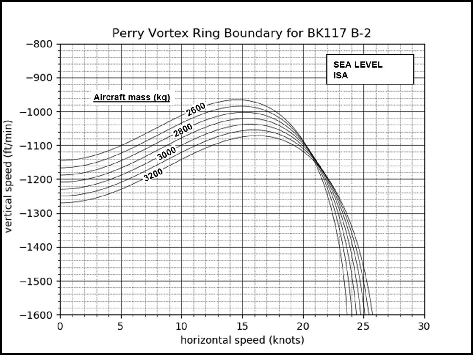
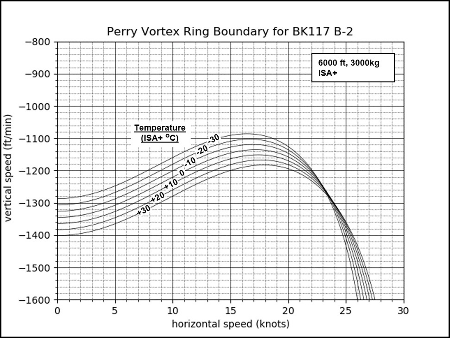
- In the absence of this information, pilots commonly rely on rules of thumb to avoid VRS. Having to rely on ad-hoc procedures to avoid VRS is no substitute for having properly constructed graphs to hand that represent the location of the VRS onset boundary on the flight envelope as a function of the helicopter’s weight and the temperature-corrected altitude (see examples in Appendix 3, Figures 19 and 20). This lack of essential information increases the risk of pilots inadvertently entering VRS during routine flight operations.
- The absence of VRS information in the helicopter’s Flight Manual did not directly contribute to this accident. However, when this information is not available to a pilot, they are limited in their ability to anticipate and avoid VRS-conducive conditions. The provision of this information in all rotorcraft flight manuals would give pilots the best possible chance to avoid VRS.
Vortex Ring State alerting systems
Safety issue: Not all helicopters have a timely VRS alerting function installed, so that pilots can avoid entering flight conditions that may develop into VRS. The safety objective of an alerting function is to significantly reduce the number of accidents caused by inadvertent entry into VRS.
- The early signs of VRS cannot always be recognised by pilots unless they have been specifically trained to recognise them. The symptoms of incipient VRS differ from helicopter to helicopter, but include:
- subtle changes in the vibration and noise from the rotor
- wallowing in the trajectory of the aircraft
- less precise response to controls
- These symptoms are the precursors to those experienced when the aircraft is in fully developed VRS, which include:
- increased rotor vibration and unsteadiness
- thrust and torque fluctuations
- loss of control effectiveness, and counter-intuitive control response
- uncontrolled sudden increase in the rate of descent.
- VRS alerting systems are new technology with potential to improve flight safety by alerting the pilot to avoid the flight conditions that may develop into VRS. While this technology is installed on some new helicopters it would be technically difficult to retrofit most older helicopter models
Emergency locator transmitter (ELT)
- In the event of an aircraft accident, the primary function of an ELT is to automatically activate and transmit an encoded signal to the Cospas-Sarsat satellite network and subsequently a notification to the RCCNZ.
- The helicopter was equipped with an Artex C406-1HM ELT, mounted on the right side of the tail boom mounting cone. The ELT is designed to activate automatically on detection of impact g-forces over 2.3 g in the forward direction and 12.5 g in the other five perpendicular axes (rear, left, right, up and down).
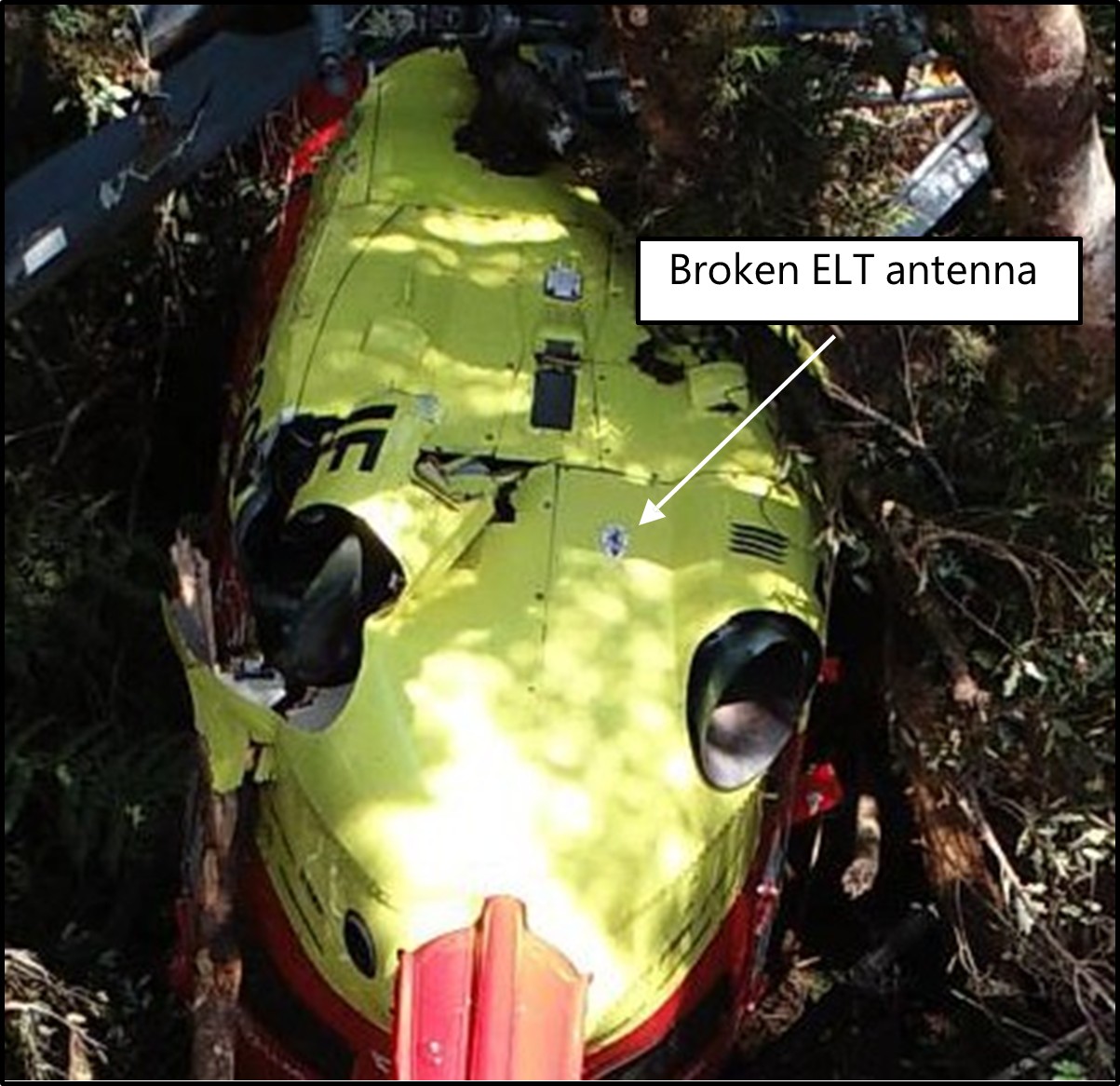
- The ELT had a rod-type antenna mounted on the top of the right rear cowling. A photo of the helicopter at the staging area shows an intact antenna, but it was found broken at the accident site, suggesting that it broke off during the accident sequence (see Figure 15).
- During interview, the crew member said that they heard the ELT’s audio alert after impact. Also, the pilot observed a red light emitting diode (LED) flashing on the ELT’s cockpit remote switch, indicating that the ELT had activated during the accident sequence.
- The ELT activated as intended, but was unable to transmit a signal because its antenna broke off during the accident sequence. As a consequence, RCCNZ did not receive a notification from the ELT.
- The Commission has previously made recommendations to the CAA to improve the performance of ELTs (Transport Accident Investigation Commission, 2014 and 2023). The importance of technology in tracking and locating has been an item on the Commission’s Watchlist since 2015 (Transport Accident Investigation Commission, Watchlist 2024). These technologies improve people’s chances of surviving aircraft accidents and incidents.
Appendix 1. Wreckage examination


Appendix 2. Operator’s standard winch circuit
Appendix 3. Predicted VRS onset boundaries for the BK117 B-2 helicopter