Two broken springs in the landing gear of an ATR passenger aircraft caused it to divert and make an emergency landing. Little damage, no injuries. Springs broke when cracks formed due to corrosion. Operator found no other such problematic springs on its ATR72 fleet, has new maintenance & replacement plan. Manufacturer updated maintenance manual worldwide, added training scenario based on this incident
Executive summary Tuhinga whakarāpopoto
-
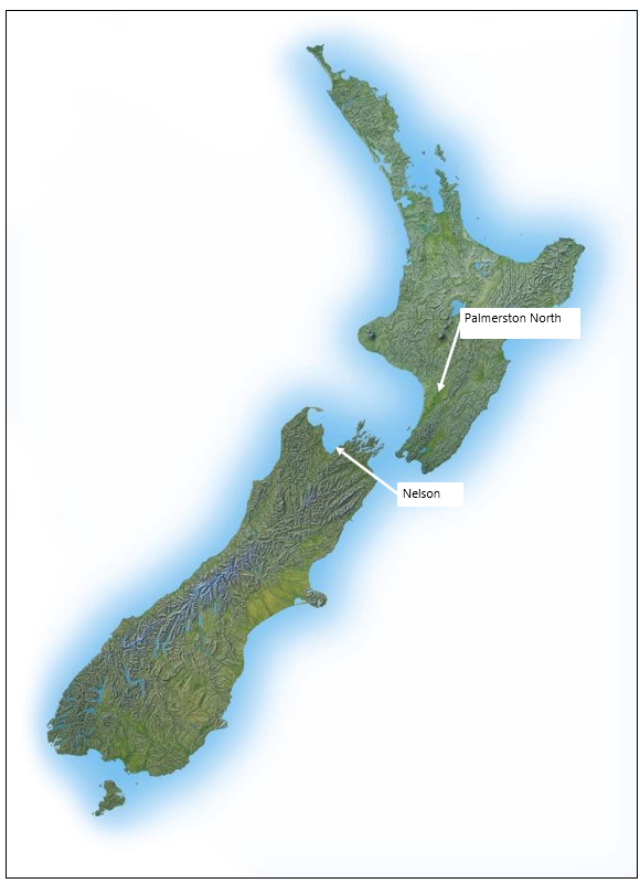
On 9 April 2017, an ATR72 aeroplane was on approach to land at Nelson with 71 persons on board. When the crew lowered the landing gear, they received an alert that the right-hand main landing gear was not locked in the down position.
- Unable to resolve the issue using the standard procedures, the crew diverted the aeroplane to the more suitable Palmerston North Aerodrome, where they made a successful landing. The landing gear did not collapse on landing and damage was limited to one burst tyre. Nobody was injured.
- The Transport Accident Investigation Commission found that the landing gear problem was caused by the failure of the two landing gear locking springs, designed to hold the right-hand landing gear in a down and locked position, and that the springs failed because of corrosion induced cracking. Salt, as a result of the saline environment in which the aeroplane was operated, was considered as the likely initiator of the corrosion.
- The Commission also found one safety issue, that the maintenance inspection programme for the locking springs would have been unlikely to detect the corrosion cracking in the locking springs prior to their failing, and that there was no required preventive maintenance of the locking springs to limit the extent of corrosion damage.
- The Commission also found that the crew’s decision to divert to Palmerston North Aerodrome was appropriate and the preparation for the emergency landing was well conducted in accordance with company procedures. However, the crew’s raising and lowering the landing gear several times before the emergency landing was outside the documented procedures and had the potential to exacerbate the condition.
- Because of the safety actions taken by the operator and aeroplane manufacturer, no new recommendations were made.
- The key lessons arising from the inquiry:
- this incident demonstrates the importance of a pre-flight visual inspection of critical components such as those of the landing gear, particularly when the integrity of the components relies on pre-flight visual inspections
- although on this occasion re-cycling the faulty landing gear did not have any adverse outcome, this action was not in accordance with flight crew operating manual procedures. In other failure cases, recycling can exacerbate the extent of the problem
- aircraft recorders provide a valuable source of information for an investigation. Operators should enforce strict adherence to post-accident and incident procedures for preserving the data on any on-board recorder.
Factual information Pārongo pono
Narrative
- At about 1330 on Sunday 9 April 2017, ZK-MCY, an ATR72-212A aeroplane (the aeroplane) operated by Mount Cook Airline (the operator), departed Auckland on a scheduled flight to Nelson. On board were 66 passengers and five crew. The first officer was the ‘pilot flying’, with the captain performing the duties of the ‘pilot monitoring’. The normal two-person cabin crew was augmented by a third cabin attendant, who was conducting a check of the rear cabin attendant.
- The flight crew had earlier flown another flight on a different ATR aeroplane. Prior to the incident flight, the first officer had conducted the pre-flight inspection of the aeroplane and had not identified any defects. The departure, climb and cruise phases of the flight were uneventful.
- At about 1435 the crew commenced the ‘before landing’ checklist as the aeroplane was approaching Nelson from the north for runway 02. The landing gear lever was selected to down, and soon afterwards both pilots noticed that the light for the right main landing gear continued to show red, indicating that the right main landing gear was not in the down and locked position. The secondary landing gear lights indicated the same status of the right main landing gear.
- The first officer commenced a ‘go around’ while the captain advised the tower controller of the situation and initial intentions. The controller acknowledged the call and, after the aeroplane had overflown the runway at about 1,000 feet (300 metres (m)), advised the crew that the staff in the tower could see “nothing untoward” with the landing gear. The crew obtained clearance to hold in visual flight conditions in Tasman Bay north of Rabbit Island at 2,000 feet (610 m), while they investigated the unsafe indication. The rear cabin attendant made an announcement for passengers to remain in their seats as the aeroplane completed the go around.
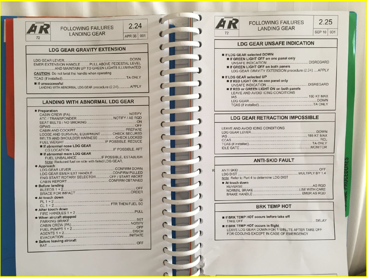
- Once established in a holding pattern north of Rabbit Island, the crew completed the ‘landing gear unsafe indication’ checklist, followed by the ‘landing gear gravity extension’ checklist (see Appendix 1). The right main landing gear unsafe indication light remained illuminated. The captain made an announcement to the passengers that there was an abnormal landing gear indication and they were completing the appropriate checks before returning to Nelson.
- The flight crew reviewed their actions and agreed to recycle the landing gear using the normal control lever to firstly retract the landing gear before selecting the gear down again. The crew did not comprehensively assess possible ramifications (air traffic control and cockpit voice recordings confirm this) before taking this action, or seek any external technical advice before recycling the gear. The landing gear retracted normally, but the right wheel unsafe light illuminated again after the landing gear was selected down for the second time. The crew again completed the relevant landing gear checklists without success.
- The flight crew discussed their options and agreed that Palmerston North, with its longer runway and weather conditions (the pilots had observed the weather conditions in the Manawatū area during the flight south), was the preferred aerodrome for landing. A ‘Pan Pan’ call was made and updated Palmerston North weather information obtained. The crew determined that the weather was suitable and requested an air traffic control clearance to fly to Palmerston North. The crew also requested emergency services to be in attendance on arrival at Palmerston North.
- The landing gear was retracted and the ‘after take-off’ checks were completed as the aeroplane climbed to 15,000 feet (4,600 m) and headed towards Palmerston North. The captain called the rear cabin attendant using the interphone and gave a briefing on the situation and intended actions (for this model of ATR there was only one cabin interphone, located at the rear of the cabin). The rear cabin attendant advised the captain that during the approach to Nelson they had heard an abnormal ‘loud clunk’ or ‘popping’ noise as the main landing gear was being lowered. The rear cabin attendant briefed the other two cabin attendants and they discussed the actions required in preparation for landing at Palmerston North. The rear cabin attendant briefed the passengers using the public address system before the three cabin attendants prepared the cabin for an emergency landing.
- The operator’s duty pilot called the air traffic service provider to offer assistance. The air traffic supervisor relayed the request directly to the crew, and the parties confirmed that all possible actions had been undertaken to try to rectify the unsafe main landing gear indication. The duty pilot also confirmed that the operator’s staff at Palmerston North had been briefed and were prepared for the aeroplane’s arrival.
- At about 1550 the aeroplane entered a holding pattern near Palmerston North at 11,000 feet (3,350 m). After about 10 minutes, the aeroplane descended to 3,000 feet (915 m) to increase the fuel consumption. This reduced the time required to burn excess fuel prior to commencing a visual approach to land. The captain took over the duties of pilot flying and the two pilots discussed the actions they would each take during the approach and landing, and the various scenarios that might occur. They reviewed the ‘landing with abnormal LDG [landing] gear’ checklist, which included an instruction to shut down both engines on landing and information on what aeroplane systems would be lost as a result.
- At 1615 the landing gear was lowered for the third time and the crew repeated the relevant checklists for the right unsafe main landing gear indication without success. The autopilot was disconnected and the captain entered a series of steep turns to increase the ‘g’ loading in an attempt to force the landing gear into the locked position. This was also unsuccessful.
- At about 1635 the captain positioned the aeroplane for a visual approach to runway 07. The tower controller confirmed emergency vehicles were in position and cleared the aeroplane to land. The first officer acknowledged the clearance and advised that they would be stopping on the runway. At about 200 feet (60 m), the first officer announced over the cabin address system, “This is the flight deck, brace for impact, brace for impact”.
- The captain landed the aeroplane on the left main landing gear before lowering the right gear and nose gear onto the runway. The power levers were closed and the first officer shut down both engines. Emergency brakes were selected and the aeroplane was brought to a halt on the runway.
- The captain instructed the passengers to remain in their seats before informing the rear cabin attendant to commence disembarking the passengers using the normal entry/exit door. The passengers were then instructed to leave their cabin baggage behind and vacate the aeroplane through the rear passenger door. The third cabin attendant moved to the bottom of the stairs and directed the passengers to assemble at the rear of the aeroplane on the runway. The passengers were then met by rescue services and taken by bus to the terminal. The crew secured the aeroplane before they too were taken to the terminal..
Site and aircraft information
Site information
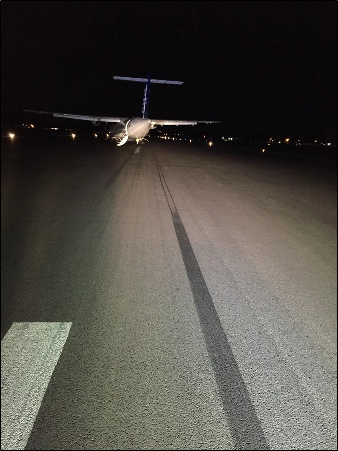
- The aeroplane landed on runway 07 at Palmerston North (runways are identified by their magnetic alignment, rounded to the nearest 10° increment. Runway 07 is aligned about 070° magnetic). The aeroplane had come to a stop approximately 1,400 m from the start of the runway – approximately 500 m before the far end. The aeroplane had stopped near the centre of the runway, heading about 10º to the left of runway alignment. The right outer main tyre was found deflated. A skid mark led to this tyre, showing that the wheel had locked and skidded about 150 m before bursting (see Figure 1).
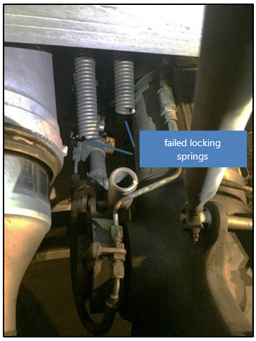
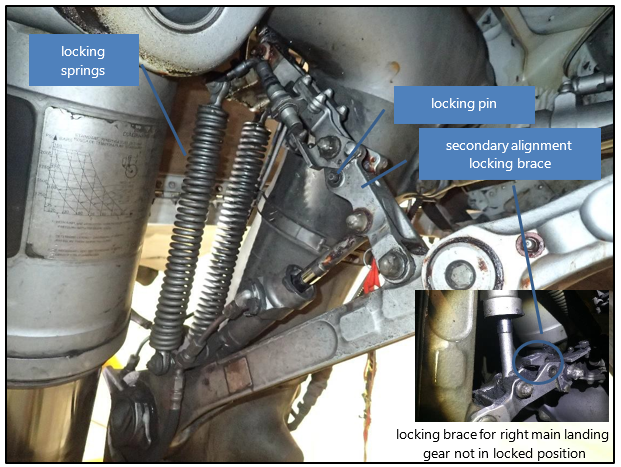
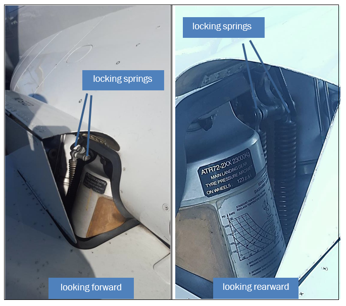
- An examination of the right main landing gear found that the two locking springs that pulled the secondary alignment brace into an over-centre locked position had broken. The two springs were still attached at each end and the locking mechanism had not fully engaged (see Figures 2 and 3). The CVR was removed and a download of flight data information from the quick-access recorder was completed. See section 0 for further information on the recorders.
Aircraft information
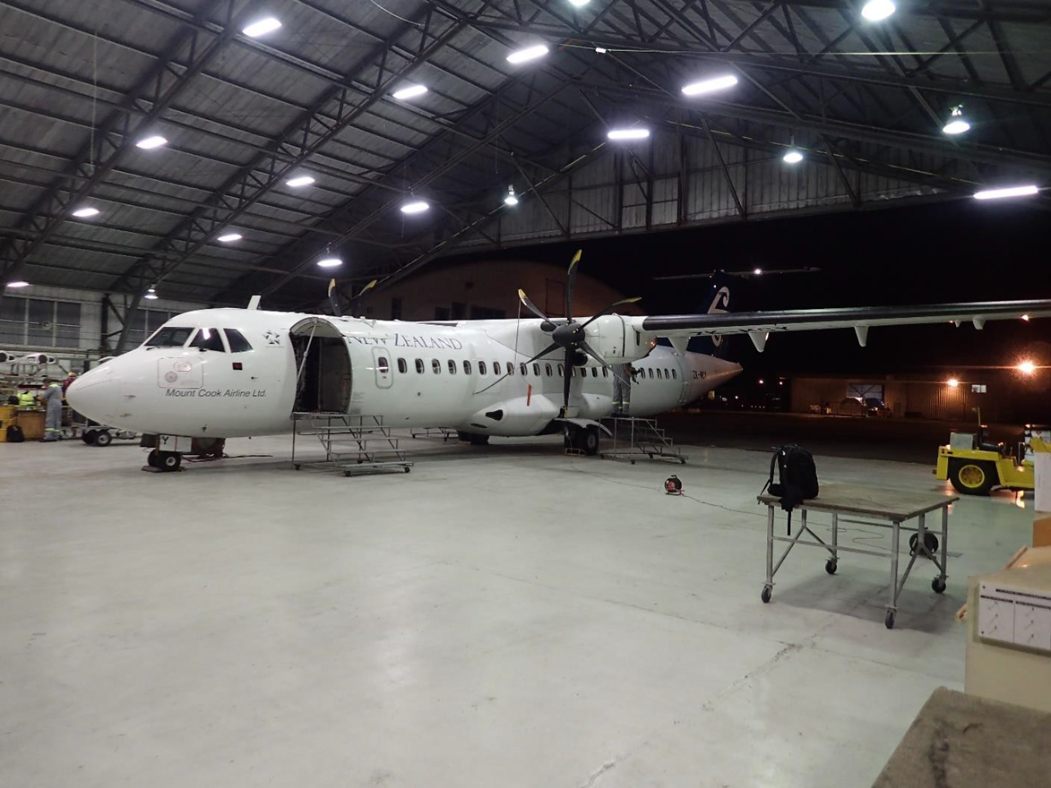
- The ATR72 is a twin-engine turboprop (the propeller (prop) is driven by a turbine engine) aeroplane, manufactured by the joint French-Italian manufacturer ATR, headquartered in Toulouse, France. The ATR72 (capable of carrying a maximum of 72 passengers), a development of the ATR42, first flew in 1988. The ATR72-212A (the ATR72-212A was marketed as the ATR72-500), the version flown by the operator, first entered service in 1997 and was powered by two Pratt & Whitney Canada PW127F turboprop engines, driving Hamilton Standard six-bladed propellers. The operator’s fleet of aeroplanes was configured to carry 68 passengers. ZK-MCY had been manufactured in 2003 and immediately entered service with the operator.
Main landing gear
- The aeroplane had a typical tricycle landing gear configuration, with a nose gear and two main landing gears, each with two wheels. The landing gear was raised and lowered into the fuselage by hydraulic pressure (in the event of a hydraulic system failure, the landing gear could be manually released to free-fall into position for landing), controlled by a position lever located on the instrument panel. Two independent indication systems, a primary on the instrument panel and a secondary on the overhead panel, confirmed the position of each gear.
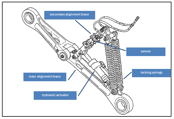
- The left and right main landing gear were mirror images and included a side brace assembly to extend or retract the landing gear leg (see Figure 4). Two identical locking springs, part number D23209000 (the springs for the left and right main landing gear, and the nose landing gear, all had the same part number), pulled the secondary alignment brace into an over-centre down-lock position. For retraction, a hydraulic actuator released the down lock. Two proximity switches, for the primary and secondary indicating systems, detected when the secondary alignment brace was in the fully down and locked position. A pin could be manually inserted through two holes in the alignment arm to prevent accidental retraction during towing or maintenance work.
- The complete right main landing gear assembly, including the side brace assembly and locking springs, fitted to ZK-MCY had originally been fitted to ZK-MCX, another of the operator’s ATR72 aeroplanes, at manufacture in 2002. The maintenance schedule for the main landing gear directed a full overhaul every 18,000 cycles (a cycle comprises one take-off and one landing) or eight years, whichever occurred first (in 2015 the frequency of the overhaul was changed to every 20,000 cycles or nine years). In mid-2009 the main landing gear had been removed from ZK-MCX for its scheduled overhaul. The landing gear had then been refitted to ZK-MCY in November 2009.
- The landing gear assembly was also required to be inspected every 5,000 flight hours as part of the aeroplane’s ‘C Check’ maintenance schedule. This was a visual inspection and did not require the removal of components. The failed locking springs had been subject to eight ‘C Check’ inspections, the latest being carried out in the period 23 July to 19 August 2016. At the time of the occurrence, the side brace and locking springs had accrued 1,420.1 flight hours and 1,456 flight cycles since the ‘C Check’, and a total 35,829 flight hours and 36,366 flight cycles in its 14 years in service.
Personnel information
- The captain held an airline transport pilot licence (aeroplane), a ‘C category’ (with the exception of specialist instructors, ‘C category’ is the first qualification for an instructor pilot) instructor rating, and a class 1 medical certificate valid until 18 October 2017. The captain had joined the operator in June 2013 as a first officer, and upgraded to captain in September 2015. The captain had accrued a total of 5,500 flying hours, including 2,000 hours on the ATR.
- The captain’s most recent flying competency check had been on 1 December 2016. The captain commented that one of the emergencies performed during the flight simulator assessment, which formed part of the competency check, was an unsafe main landing gear indication. During the simulator session the fault had been rectified by completing the checklists for the unsafe landing gear indication and landing gear gravity extension.
- The captain had flown 25 hours in the preceding week, including working the two days preceding the occurrence. The captain commented that they had no medical concerns and had been fit to fly on the day of the occurrence.
- The first officer held a commercial pilot licence (aeroplane) and class 1 medical certificate valid until 12 September 2017. The first officer had joined the operator in October 2013 and had accrued a total of 3,107 flying hours, including 1,870 hours on the ATR.
- The first officer’s most recent competency check had been on 18 November 2016. Like the captain, the first officer commented that during the simulator assessment that formed part of the competency check, one of the emergencies performed was an unsafe main landing gear indication. During that simulator session too, the fault had been rectified by completing the checklists for the unsafe landing gear indication and landing gear gravity extension.
- The first officer had been off duty the day before the occurrence and had flown 10 hours in the preceding week. The first officer commented that they had no health concerns and had been fit to fly on the day of the occurrence.
Recorders
Flight data recording
- A copy of the flight data information for the flight was obtained. The data recorded that the landing gear lever was first selected to down as the aeroplane descended past 1,400 feet (425 m) on the approach to Nelson. The aeroplane was travelling at 154 knots (285 kilometres per hour [km/h]) airspeed at this time (the maximum allowed speed for lowering the landing gear was 170 knots (315 km/h)). In the next 6-11 seconds the nose and left main landing gear locked in the down position. The right main landing gear remained unlocked. The data showed a similar sequence for the following two times the gear was lowered before landing.
- The recorded data showed that while holding near Palmerston North, after the landing gear had been lowered and the autopilot disconnected, the aeroplane was rolled to nearly 50º angle of bank, both left and right. The aeroplane was then configured for the landing with full flap selected and rudder control yaw damper disengaged on final approach. At about 500 feet (150 m) the master warning light was recorded as illuminating, indicating that the landing gear was not locked down for landing (the landing gear warning bell activates at the same time). The aeroplane touched down at 92 knots (170 km/h) with 4.6º of left bank. The power levers were closed and at 61 knots (115 km/h) both engines were shut down. The aeroplane came to a stop 13 seconds later.
Cockpit voice recording
- The aeroplane was fitted with a CVR capable of holding two hours of recording on a continuous loop. Nearly two hours elapsed between the landing gear being first selected down approaching Nelson and the aeroplane landing at Palmerston North. The recorder should therefore have captured this period of time.
- The recording of the flight commenced with the rear flight attendant instructing the passengers to remain seated following the initiation of the overshoot (a discontinued approach to land) at Nelson. The last 12 minutes of the recording were of the maintenance personnel at Palmerston North after the incident, turning on aeroplane power, starting the engines and taxiing the aeroplane to the apron near the terminal. This portion of the recording overwriting the period when the crew were first alerted to the failure. Nevertheless, the recording was of good quality and supported the evidence provided by the crew in their interviews.
- A copy of Nelson control tower radio transmissions was obtained covering the period in which the crew of the aeroplane were talking on that frequency.
Test information
- The two broken locking springs from the aeroplane, serial numbers MN1276 (right rear) and MN1282 (right forward), were subjected to metallurgical examination by Quest Integrity (Quest). See Appendix 2 for a summary of the examination report.
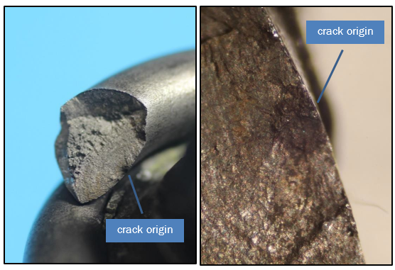
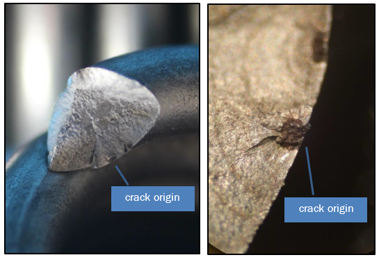
- The examination found that the locking springs failed as a result of stress corrosion cracking followed by fatigue initiated corrosion. The cracking then propagated until the section of spring could no longer support the load and failure occurred. The corrosion crack originated on the inside diameter surface of the springs (see Figures 5 and 6).
- The fracture surfaces of the two locking springs were almost identical in appearance. Quest was unable to determine if they had failed at the same time. Quest commented that while the springs were made of stainless steel, they were not immune to chloride (salt) induced corrosion and stress cracking.
- Safran requested that it be able to examine the two failed springs. It was agreed that spring MN1282, the forward spring only, be provided. The Commission obtained a third spring from the operator’s ATR72 fleet for comparison. This spring had accumulated 42,012 cycles, compared to the 36,366 cycles of the failed springs. It was also provided to Safran.
- The examination by Safran found that the forward spring (MN1282) failure was initiated by intergranular corrosion (an attack on the grain boundaries of a metal. See paragraph 4.2.4 for further information) that then expanded by stress corrosion cracking followed by fatigue. The identification of chlorine and sodium suggested that the environment might have influenced the onset of the corrosion. See Appendix 3 for a summary of the examination report. The third spring was not inspected. It was instead used to develop a potential ‘new inspection process’ during overhaul.
Analysis Tātaritanga
Introduction
- The right main landing gear did not lock down because the two locking springs had failed. The failure of either one or both springs was very likely to have been the cause of the unusual noises the cabin crew heard when the landing gear was lowered on approach to Nelson.
- The failure of the locking springs to pull the over-centre lock into place meant that the two proximity position switches detected the abnormal landing gear position. This detection resulted in the circuit for the primary and secondary indication lights not being made. This was subsequently displayed to the pilots on the instrument panels, alerting them to the unsafe condition of the right landing gear.
- The failure of both springs meant that the emergency checklist for an unsafe landing gear indication was ineffective in correcting the fault. The crew were therefore required to conduct a landing at a suitable aerodrome with the possibility that the landing gear would collapse on landing.
- The following analysis discusses why the locking springs failed. It also discusses the crew’s actions in diverting to Palmerston North, the checklists used by the pilots and other safety considerations.
Locking spring failures
- The landing gear locking springs formed part of the main landing gear assembly. A similar spring, but with a different part number, was also installed on the nose landing gear. The locking springs were confirmed by the manufacturer as having been manufactured in accordance with design specifications.
- The cracking in each spring originated on the inside of the coil facing the major axis or centre of the spring. The inside diameter of a spring was subject to greater stress than the outside diameter. When the landing gear was extended, the springs passed through the point of maximum tension and continued to remain under tension in the down and locked position. This tension resulted in the extension of the springs, which exposed the inside of the springs to the elements, where foreign matter could collect and where salts could concentrate. The aeroplane was operating in a corrosion environment that was classified as ‘severe’ according to the Federal Aviation Administration’s Advisory Circular 43-4B (AC 43-4B).
- Metallurgy examinations of the locking springs found that both failed because of intergranular corrosion followed by stress corrosion cracking and fatigue. The springs finally broke in overload. The corrosion was likely initiated by salt depositing on the springs and over time reacting with the stainless steel.
-
AC 43-4B outlines the different forms of corrosion. A summary of the relevant forms is provided below:
1.Intergranular corrosion is a chemical reaction of oxidation on the grain boundaries of a metal. The metal consists of quantities of tiny individual grains, and each grain has a clearly defined boundary that chemically differs from the metal within the grain. The grain boundary and the grain centre can react with each other as anode and cathode when in contact with an electrolyte (such as salt).
2.Stress corrosion cracking involves a constant or cyclic stress acting in conjunction with a damaging chemical environment.
3.Corrosion fatigue involves the combination of cyclic stress and corrosion and occurs in two stages. First, corrosion and cyclic stress damage the metal by pitting and crack formation. Next, the crack propagates, often spreading from corrosion pits. Fracture of a metal part by fatigue corrosion generally occurs at a stress level far below the fatigue limit in laboratory air.
- Examining the requirements for relevant forms of corrosion, it is evident that the cyclical stress of extending and retracting the landing gear, combined with the corrosive environment in which the aeroplane operated, increased the likelihood of corrosion occurring.
History of spring failures
- The aeroplane manufacturer and the manufacturer of the springs held records for a total of 19 locking spring failures. The aeroplane manufacturer advised it had received 13 reports of landing gear locking springs failing in service since 2005. All 13 occurrences had involved the failure of a single spring, of which seven involved the main landing gear and six the nose landing gear. This occurrence, the 14th, was the first dual in-service failure.
- Six of the 13 failures had been from a batch of incorrectly manufactured locking springs (service Bulletin 631-32-201, issued 19 May 2010, recommended the replacement of the subject locking springs. The operator’s fleet of ATR72 aeroplanes did not include this batch of locking springs). Four had been the result of “mis-installation of the nose landing gear locking spring link”. The springs from the remaining three failures had not been recovered, so the cause had not been identified. There was no record of the flight cycles for any of the failures.
- The aeroplane manufacturer provided information from the manufacturer of the landing gear locking spring, which showed that it had received a further six reports of spring failure between 2006 and 2012. Five of the six failures had involved operators from the South East Asia region. Reports on three of the six failures recorded “corrosion pitting” as a cause. A fourth stated that “oxidation was found near origin”. Laboratory test reports were not available for the remaining two failures. Flight cycles before failure were provided for four of the six reports, which showed that these springs had failed after their first overhaul.
Landing gear
Landing gear design
- The design of the main landing gear meant that, with both springs in a failed condition, a large sideways force when there was little or no weight (downwards force) on the wheels could have caused the landing gear to collapse. Once the aeroplane had landed and there was full weight on the wheels, the landing gear could not collapse. This explains why the right landing gear did not collapse on landing despite the two failed springs.
-
When designing the landing gear, the manufacturer had conducted a system safety assessment to ensure an acceptable level of safety existed. The system safety assessment had examined the likelihood of failures and the resulting consequences. There were five consequence ratings:
1.No Safety Effect: Failure Conditions that would have no effect on safety; for example, Failure Conditions that would not affect the operational capability of the aeroplane or increase crew workload.
2.Minor: Failure Conditions which would not significantly reduce aeroplane safety, and which involve crew actions that are well within their capabilities. Minor Failure Conditions may include, for example, a slight reduction in safety margins or functional capabilities, a slight increase in crew workload, such as routine flight plan changes, or some physical discomfort to passengers or cabin crew.
3.Major: Failure Conditions which would reduce the capability of the aeroplane or the ability of the crew to cope with adverse operating conditions to the extent that there would be, for example, a significant reduction in safety margins or functional capabilities, a significant increase in crew workload or in conditions impairing crew efficiency, or discomfort to the flight crew, or physical distress to passengers or cabin crew, possibly including injuries.
4.Hazardous: Failure Conditions which would reduce the capability of the aeroplane or the ability of the crew to cope with adverse operating conditions to the extent that there would be:
i. a large reduction in safety margins or functional capabilities;
ii. physical distress or excessive workload such that the flight crew cannot be relied upon to perform their tasks accurately or completely; or
iii. serious or fatal injury to a relatively small number of the occupants other than the flight crew.
-
Four quantitative probability ranges were further defined for determining the likelihood of an event occurring:
1.Probable: those having an Average Probability Per Flight Hour greater than of the order of 1 x 10⁻⁵.
2.Remote: those having an Average Probability Per Flight Hour of the order of 1 x 10⁻⁵ or less, but greater than of the order of 1 x 10⁻⁷.
3.Extremely Remote: those having an Average Probability Per Flight Hour of the order of 1 x 10⁻⁷ or less, but greater than of the order of 1 x 10⁻⁹.
4.Extremely Improbable: those having an Average Probability Per Flight Hour of the order of 1 x 10⁻⁹ or less.
- The manufacturer’s assessment of a (single) locking spring failure was that it would have ‘No Safety Effect’. This was due to each landing gear having two locking springs, each capable of locking the landing gear in the down position. The failure of one spring did not induce additional stress on the remaining spring. The manufacturer further determined that the consequences of both springs failing would be ‘Major’. ‘Major’ failure conditions are required to be no more frequent than ‘Remote’.
- This was the first double-spring failure reported to the manufacturer. The international aeroplane fleet had flown more than 30 million (3 x 10⁷) flight hours at the time of the incident, which was within the ‘Extremely Remote’ probability range for a double-spring failure to occur. Nevertheless, as locking springs remain in service in potentially corrosive environments, it is important that appropriate maintenance and inspection procedures are in place to ensure that double-spring failures do not occur.
Routine maintenance of the locking springs
Safety issue: The maintenance inspection programme for the locking springs would have been unlikely to detect the corrosion cracking in the locking springs prior to their failing, and that there was no required preventive maintenance on the locking springs to limit the extent of corrosion damage.
- ATR advised that there was not a “specific life limit for the springs as it is not a primary structural element. The parts having a life limit are the ones whose failure may lead to the landing gear collapse. A single failure of one spring doesn’t lead to the landing gear collapsing” (emphasis added). As such, the springs were considered ‘on condition’ with no life limit, provided they met the inspection and overhaul requirements while in service.
- The locking springs were required to be checked at regular intervals, either individually or as part of the landing gear assembly. The checks included a general visual check before each flight, a specific visual check every 5,000 flight hours and an overhaul after 20,000 cycles or nine years, whichever occurred first.
Maintenance records
- Maintenance records showed that the right main landing gear and locking springs had been maintained in accordance with the maintenance procedures. The locking springs had also met the physical load test requirements at their most recent overhaul. At the time of failure on 9 April 2017, the two springs had each accrued a total of 36,366 flight cycles since new, 16,908 flight cycles since their last 20,000 cycle overhaul and 1,456 flight cycles since their last visual inspection.
- At 36,366 flight cycles, the failed locking springs were well above the average for the operator’s ATR fleet (the operator was in the process of upgrading the fleet to ATR72-600 models). However, the cycles were still significantly fewer than the 42,000 flight cycles for the fleet leader. The history of the two aeroplanes on which the right main landing gear and springs had been installed was typical for the operator’s fleet.
Pre-flight check
- It was not possible to determine if one of the springs had failed before the incident flight. The Flight Crew Operating Manual for the aeroplane identified that the landing gear structure was to be inspected as part of the exterior pre-flight inspection. The pilot conducting the pre-flight inspection had not identified any problems with the landing gear.
- The exterior inspection was primarily a visual check to ensure that the overall condition of the aeroplane, the visible components and equipment were safe for the flight. This inspection was almost certainly not able to identify the corrosion cracks on the inner diameter of the locking springs before they failed.
- However, a thorough inspection should be able to detect a broken spring. There are large components surrounding the main landing gear locking springs, and these do make it difficult to see the entire length of the spring from a single location. However, observing the springs from different locations would have allowed for their complete inspection, and almost certainly would have allowed for the detection of an abnormal condition (position or orientation) had one of them failed (see Figure 7).
Specific visual check
- The specific visual check required a “detailed visual inspection of the MLG [main landing gear] locking springs to be sure that they are not damaged or broken”. The specificity of this check would have almost certainly ensured that any failed locking springs were identified. Therefore, both locking springs almost certainly failed after their last specific visual check. The investigation was unable to determine if the stress corrosion cracks had been present at the time of the last specific visual check.
Overhaul
- The locking springs’ overhaul procedures required a physical load test, where each spring was removed from the landing gear assembly and affixed to a test fixture. The test involved extending the spring to a specific length and measuring the load required for extension. If the load were within the allowable range, and no defect or damage were identified, the spring passed the load test. The ability of this method to identify corrosion cracks in the spring was limited to the crack reducing the force required to elongate the locking spring or the spring failing. A visual inspection for corrosion was also undertaken as part of this check.
-
The Quest metallurgical report identified that:
The position of the fatigue initiation around the spring wire was primarily controlled by the location of highest torsional stress at the smallest radius in the spring. The size of the initial area of SCC [stress corrosion cracking] was only 0.5mm in diameter. The implication is that only small defects are required to initiate fatigue indicating that the springs are not particularly damage tolerant. In addition, surface SCC and cracking was seen in sections from areas where they had been inspected by fluorescent dye penetrant testing and shown to be crack free i.e. dye penetrant testing was not reliable to find the cracking seen. Taking all of this into account it is highly unlikely that a suitable reliable inspection technique could be used to prove the long term safety of the springs.
- Therefore, it is unlikely that the stress corrosion cracks that resulted in the failure of the locking springs could have been detected during any of the routine maintenance inspections. Instead, the pre-flight visual inspections to identify a failed locking spring, and the redundancy of having two locking springs were the principal mechanisms in place to avoid the double-spring failure that occurred on the accident flight.
- It might appear coincidental that both springs failed at the same time. However, as mentioned above, it could not be determined with any certainty whether one spring failure preceded the second failure.
- Following this occurrence, the operator began a programme of replacing high-time locking springs. Priority was given to springs that had accumulated more than 30,000 flight cycles. The manufacturer of the aeroplane also began reviewing the inspection procedures for the locking springs to determine if an additional inspection procedure could be implemented to identify corrosion and subsequent cracking such as that which resulted in the failure of the locking springs. See section 7 (safety actions), for further information on the safety actions taken.
Additional aircraft maintenance requirements
- The ATR72 aeroplane was subject to a ‘Corrosion Prevention and Control Programme’ (CPCP) managed by the manufacturer. The CPCP was in place for the entire life of the aeroplane, and was designed to limit the extent of corrosion damage to the aeroplane and its components. It placed additional requirements on the maintenance of the aeroplane in the form of inspections, cleaning and protection. The locking springs were not specifically mentioned in the manufacturer’s documentation for the CPCP, as the landing gear was not addressed by this document.
- The CPCP document included a ‘corrosion severity map’ of the world, which matched that contained in AC 43-4B. It categorised regions depending on the potential for corrosion to occur. There were three classifications that dictated the periods between preventive maintenance actions. New Zealand was categorised as a region with the highest susceptibility to corrosion, known as a ‘severe zone’. This required the preventive maintenance procedures to be undertaken at the highest frequency.
- The Quest metallurgical report identified that dirt and debris were present on both springs. This indicated that they were unlikely to have been subject to any cleaning procedure. Furthermore, the Quest metallurgical report identified that cleaning the springs would have likely reduced the risk of salt concentration on the locking springs, which contributed to the corrosion.
Operational considerations
Diversion to Palmerston North
- The flight crew elected to divert to Palmerston North rather than land at Nelson or one of the other possible aerodromes in the general area – Woodbourne (Blenheim) and Wellington. The flight crew were more familiar with Palmerston North, having regularly flown there, including several days previously. The geography of Palmerston North meant that, should the landing gear collapse on landing and the aeroplane depart the runway, there was less risk of the aeroplane crashing into an obstacle than there was at some of the other available aerodromes. With an available landing distance of 1,763 m, runway 07 at Palmerston North was longer than all the other runways except one of the Wellington runways.
- The rescue services available at Palmerston North, supported by local emergency services, and the hospital being nearby meant that there were sufficient services available should they be required. Finally, the crew had observed the weather conditions in the Palmerston North area as they flew south and knew them to be suitable. To confirm this, they obtained the latest weather information, which confirmed the conditions to be clear and nearly calm. This ensured the crew were able to focus on flying the aeroplane and did not have to worry about the wind or having to fly an instrument approach to get below any cloud.
- The diversion to Palmerston North was therefore considered to have been an appropriate choice.
Checklists
Recycling the landing gear
- Checklists are promulgated by the manufacturer and the operator of an aeroplane to support the operating crew. This enables a crew to operate as an effective team in a standardised manner and help prevent unintended consequences. The checklists are based on known or predicted conditions and are updated as experiences and unforeseen events occur. Pilots should, therefore, always adhere to a checklist to ensure an appropriate response to a situation. Pilots do, however, have a responsibility to ensure the safe conduct of flights and therefore have discretion to take any action they consider appropriate based on their training, experience and knowledge of the situation. When doing so, they should consider the potential consequences of any actions they take.
- The aeroplane checklists stated that following a confirmed indication of an unsafe landing gear, pilots were directed to the ‘landing gear gravity extension’ checklist. If this was unsuccessful, pilots were further directed to the ‘landing with abnormal landing gear’ checklist.
- In this occurrence, the flight crew were responding to a mechanical warning that the right main landing gear had not locked down. The flight crew, in attempting to lower the landing gear, recycled the landing gear, an action not included in the checklists for the aeroplane. Prior to this action, the Nelson tower controller had said that there appeared to be nothing untoward. This information was limited to the observation that the wheels appeared to be down, but the crew had no means of determining positively whether the landing gear was fixed in place.
- There was no evidence that the crew comprehensively assessed the potential consequences associated with recycling the landing gear during their decision making process. This assessment would have likely identified that the landing gear may have become stuck at an intermediate position. A comprehensive assessment would have also likely identified that external advice was available, for example contacting the duty pilot and liaising with the operator’s engineering staff, which would have allowed further assessment of the possible ramifications. There was ample fuel and time available to achieve this.
- While the flight crew’s actions to recycle the landing gear did not affect the outcome of this occurrence, these actions were outside the checklists contained in the flight crew operating manual procedures. In other failure cases, recycling might worsen the situation. The manufacturer confirmed this analysis and reiterated the need to follow the checklists.
Engine shutdown
- The ‘landing with abnormal landing gear’ checklist directed that at touchdown both engines were to be shut down. This action results in the loss of a number of services, including reverse thrust, nose wheel steering and normal brakes. The loss of these services increases the landing distance and has the potential to make control of the aeroplane on the ground more difficult. The burst tyre on the right side and the associated skid mark suggested that the captain had to use heavy braking to prevent the aeroplane leaving the left side of the runway.
- The manufacturer advised that, in the event of a main landing gear collapse, the propeller on that side would strike the ground with unfavourable results. A gear collapse would likely be sudden and give insufficient time for the crew to react and the propeller to slow before striking the ground. The checklist was therefore predicated on the worst-case scenario and considered appropriate.
Other considerations
Cockpit voice recorder
- To remove the aeroplane from the runway, the maintenance personnel reset all the circuit breakers in preparation for starting the engines. These included the circuit breakers for the CVR that had been pulled out to protect the recording of the flight. The CVR recorded in a two-hour loop. By reapplying power to the aeroplane with the CVR circuit breakers reset, the CVR commenced recording again and so overrode a portion of the flight. The loss of part of the recording, while not critical for the investigation of this occurrence, is a reminder of the need to ensure the protection of this potentially valuable investigation resource.
Communications
- The aeroplane was fitted with one interphone only to enable the cabin crew to communicate with the pilots. The interphone was located by the rear cabin attendant’s seat. This meant that the forward cabin attendant was required to either move to the rear of the cabin to communicate with the lead attendant, or rely on visual indicators for information. This may limit the ability of cabin crew to pass on information in a timely manner.
- At the time of the occurrence the operator was in the process of replacing the 500-series of aeroplanes with newer 600-series. The later version is equipped with two cabin interphones to allow direct and immediate communication between the two cabin attendant positions, and with the pilots. The fleet replacement programme was expected to be completed during 2020.
- About two hours elapsed between the landing gear failing to lock down and the aeroplane landing at Palmerston North. This gave ample time for the pilots to analyse the situation, obtain external advice and prepare for the landing. It also gave the cabin crew time to prepare the cabin. This included individually briefing those passengers seated by windows and exits, ensuring an unaccompanied minor was appropriately managed and reassuring those in need. This in turn ensured that everything was calm and controlled during the landing and subsequent disembarkation of the aeroplane.
Appendix 1. ATR72 Landing Gear Emergency Checklists
Appendix 2. Summary of metallurgical testing undertaken by Quest Integrity
Initial Visual Examination
The locking springs were manufactured from stainless steel, typical of type 302 stainless steel that had been cold drawn to a high hardness. The diameter of the wire was 6.6 millimetres, with a total static length of 275 millimetres eye to eye. The springs were probably fabricated in accordance with specified requirements.
The right rear locking spring had failed at the fourth coil from the bottom, while the right forward locking spring had failed at the twelfth coil from the bottom. Both fractures were at 45º to the axis, indicating the failure was due to torsion in the wire.
An arc, typical of fatigue with crack arrest arcs was present on both fracture surfaces, and ran for about 1/3 of the way across the wire before overload occurred. The fatigue fracture areas were relatively smooth and were not corroded. The origins of the two arcs was on the inside of the springs. A small black region was present at the origin of both fractures. The right rear spring displayed another two cracks in the same coil as the failure.
The rear spring was sectioned along its length to separate the coils and allow further detailed examination.
Metallography
Examination of the microstructure of the rear spring found no evidence of grain boundary sensitisation, showing there was no major issues in the heat treatment of the wire prior to cold drawing.
The main crack had propagated at least 40% the way across the section. Two additional smaller cracks were present near to the main crack. Fine pitting was present where the grain boundaries in the structure were at the surface – grain boundary corrosion.
Examination of the forward spring showed similar features as seen in the rear spring. The key feature was that an area of stress corrosion cracking was present about 0.2 mm deep, which was not associated with any additional cracking.
Scanning Electron Microscopy (SEM)
Examination of the forward spring showed that there were two distinct crack origins. The fracture surface near each origin was covered with corrosion product and appeared to have features that are consistent with the sections through the areas of stress corrosion cracking.
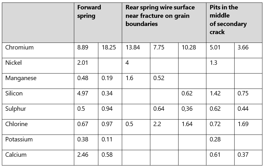
Energy dispersive x-ray analysis (EDAX) showed that this area was covered with oxide. Chloride was also detected in some areas, see Table below. Away from the origin area, the fracture was typical of fatigue/corrosion fatigue with fatigue striations with spacing close to the origin region of about 0.003 mm.
SEM examination of the rear spring revealed similar findings.
Discussion
The failures of the springs occurred as a result of minor surface corrosion and stress corrosion cracking that then propagated by fatigue/corrosion fatigue until the remaining ligament could no longer support the load and final overload failure occurred. Areas of stress corrosion cracking were present away from the points of failure. The steel used was typical of 302 stainless steel that had been cold drawn to a high hardness.
302 stainless steel is not immune to atmospheric corrosion and pitting will occur especially in marine environments especially if salts are concentrated. Austenitic stainless steels (stainless steels may be classified by their crystalline structure into four main types: austenitic, ferritic, martensitic and duplex) such as 302 are particularly prone to stress corrosion cracking induced by chloride. Furthermore, the cold drawing required to generate the tensile strength of the wire will generate residual stresses that will increase the risk of chloride stress corrosion cracking.
The position of the fatigue initiation around the spring wire was primarily controlled by the location of highest torsional stress at the small radius of the spring. The size of the initial area of stress corrosion cracking was only 0.5 mm in diameter.
Conclusion
The springs failed as a result of stress corrosion cracking followed by corrosion fatigue.